Synchronization | ||||||||
|
| |||||||
-
From the Formboard section of the action bar, click
Harness Flattening Parameters
 .
. - In the Harness Flattening Parameters dialog box, click the Synchronization tab.
- Under the Put in scale
mode during the length synchronization, choose among the below options:
- None: Modifies the extremities according to the
length of the segments during the synchronization process. The segment is not
shown in fake length.
By default, this option is selected.
- Only intermediate segments: Displays only the segments with no connectors at their extremities in fake length after the synchronization.
- All segments: Does not move the segment extremities during the synchronization process. If a segment length is modified in the original 3D design, the segment is shown in fake length. The extremities are not modified but the true length attribute is synchronized with the length of the 3D design (newly modified).
- None: Modifies the extremities according to the
length of the segments during the synchronization process. The segment is not
shown in fake length.
-
Under the Synchronize the intermediate point, choose between following options :
-
Do not
move the point:
Select this option to keep the points at the same place along
the segment even after the synchronization.
By default, this option is selected
- Move the point: Select this option to keep the original ratio of distance between each point.
Tip: When rolling segments, Do not move the point is recommended if you roll the segments within the active plane.

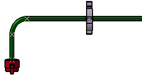
If you increase a segment length in the 3D design and synchronize the flattened geometry to take this modification into account, you get something like this:
If you select Move the point and roll the segments, segments are straightened out when you synchronize the flattened geometry after a change in length in the 3D design.
For more information, see Rolling Branches.
-
Do not
move the point:
Select this option to keep the points at the same place along
the segment even after the synchronization.
- Under the Put in scale
mode during the length synchronization, choose among the below options:
- Click OK to validate.