Rotating Segments | |||||
|
| ||||
-
From the
Formboard section of the
action bar,
click
Prepare Layout
 .
.
-
On the
context toolbar,
click the
Rotate
 .
.
-
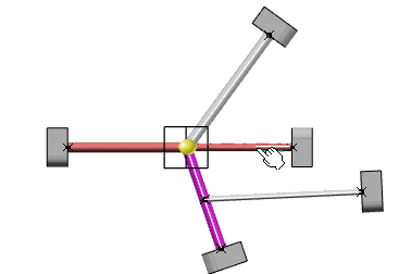
Hover the pointer over a branch or a segment to rotate.
By default, a yellow sphere
 appears at the detected pivot that is at the farthest end of the branch or
the segment. You can select the Pivot point identification by
proximity check box to detect the pivot nearest to the pointer.
For more information, see Rotate action.
Tip: Press Shift to shift the current pivot point on the opposite end. -
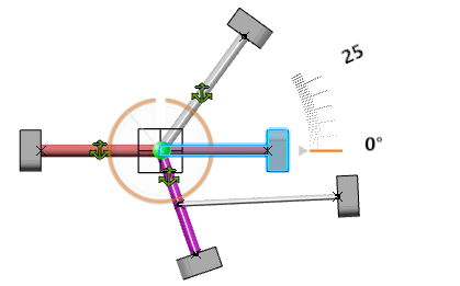
Select a branch or a segment to rotate.
- The yellow sphere
 becomes green
 .
.
- The branch is highlighted.
- The Prepare Layout context toolbar appears near the branch, to show the current option of the handle.
- The Robot automatically snaps onto the pivot point, which is the center of rotation.

Selection in the tree is impossible because the end of the branch is mandatory since the exact position of the selected point needs to be known. The branch point or branch end furthest to the point of selection is selected as the rotate point and the Robot moves on it.
In a subgeometry, several branches may be impacted by rotation and they are highlighted.
The rotation is done in a plane parallel to the active plane. The default harness flattening parameter is the one you defined in the Harness Flattening Parameters dialog box at the beginning of the session. For more information, see General Parameters.
There are two ways of selecting the rotation pivot:
-
If the branch point of a branch is selected as the rotate pivot point, the branch splits at this point and the split segments are put in a new branch.
-
If the branch end is selected as the rotate pivot point, no split is done and the whole branch is rotated.
To see a message during the branch split when you rotate the segments, select an option in Me
 > Preferences > App Preferences > 3D Modeling
> Equipment > Electrical Discipline > Electrical Harness Flattening > General. For more information, see General.
 - The yellow sphere
-
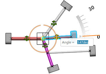
Select the branch and drag the arc to rotate.
Alternatively, you can:
- Drag the triangle to change the height value.
- Click the angle value along the ruler, enter a value in the Angle callout, and then press Enter.

A message is displayed when the angle is inferior to the one defined by default or by the business rule.
Note: The minimum angle allowed between the branches while rotating the branch is zero deg. - Optional:
To change the reference line for the angle of rotation, select the
anchor
 on the required branch with the same rotating junction.

This reference line selected for the rotation is not persistent.
-
Press
Esc to cancel the command.
You can also select another command and the rotate operation aborts. To validate the preview, click the work area background. In this case, the rotation is really executed, with a modification of the geometry content.
This may take some time depending on the amount of content to handle.
Important: - Ctrl + select the branch to rotate it with split. Otherwise the whole branch is rotated.
- The split pivot flag is visible on branch points where rotate is allowed . This split is specific to Electrical Manufacturing Preparation and after the rotate split, there is no change in the tree of 3D harness content.
- When rotating segments in a closed harness loop, the loop is automatically opened at the free end of the selected segment and a green line created to serve as a reminder that a link exists.
- Length tolerance cannot be applied on a Roll section and vice versa.
- Multiprofile segments: To avoid twisted and impossible configurations, the local V-axis of the profile, the sketch is kept aligned with the normal direction of the active plane.
- Mechanical parts: A dashed green line visualizes the link between the segment and the mechanical part. Use the Compass to reposition the part properly.