Inserting Disconnects | |||
| |||
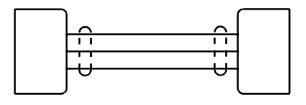
-
Create a disconnect and place the representation over the three wires.

-
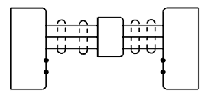
Click the disconnect and click Insert on Route
 on the context toolbar.
The disconnect is placed and the wires are split.
on the context toolbar.
The disconnect is placed and the wires are split.A new instance of each split wire is created and routed.
Notes:- Since the wires are grouped under a cable, a new instance of the cable is created and the new instances of the wire are grouped under it.
- If a shield connection is placed on the side of the new wires, the shield connection is removed from the old cable and a new one is created on the new cable. If this shield connection uses a splice and a wire, the same splice and wire instance are reused. The same geometry is reused for the new representation.

-
For each harness connector, display
the two remaining pins using the Modify Representation command.
-
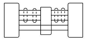
Create a cable containing two wires and connect them to the free pins.

-
Resize the disconnect representation to cover the new wires.
Note: It is possible to place the disconnect on one wire to split only one wire over the two. -
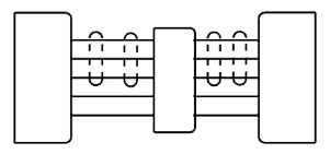
Click the disconnect and click Insert on Route .
The new wires are split. A new instance of each split wire is created and routed.
 Note: If all pins of the disconnect are displayed and connected, the disconnect is displayed with its full representation, if defined in the Data Setup. For more information, see About Electrical Component Representation.