Create a Net Group End Representation
Before you begin:

- In Data Setup, define a representation for net groups ends in the Default NetGroup Extremity Representation resource. For more information, see Electrical Logical Resources.
- Create nets.
- Create and place two equipments and connect them with the nets.
-
On the
context toolbar,
click
Manage Net Group Extremities
 .
.
-
In the
NetGroup Extremities dialog box, select the
desired representation.
The representation appears and follows your pointer.

-
In
Logical Net Group dialog box, enter a name for the
net group and click
OK.
Note: If the net group already exists, the Logical Net Group dialog box does not appear.The net group is created. The existing nets are grouped under the net group. The ports linked with the representation are highlighted and a panel appears.

-
In the panel, select one of the following options:
-
 : Validates the link between your representation and the
net ports.
Note: The suggested link is the one with the nearest ends of the nets.
: Validates the link between your representation and the
net ports.
Note: The suggested link is the one with the nearest ends of the nets. -
 : Removes the representation from the view and ends the
command.
: Removes the representation from the view and ends the
command.
-
 : Allows you to choose other ports for the link with
representation.
Note: If you select this option, you need to select to validate the selection.
: Allows you to choose other ports for the link with
representation.
Note: If you select this option, you need to select to validate the selection.
If you have selected or
, your symbol is now placed in the diagram view.
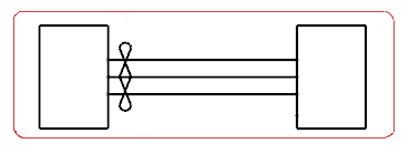
In the tree, the net group end representation is linked with the end ports of the selected nets and with the end port of the net group.
Note: If you have defined several types of representation in Data Setup, you can change the representation displayed in the diagram view by selecting it, and then clicking Manage Net Group Extremities again.
-
 .
. .
.
 .
.
