Routing Nets and Net Groups | |||||
|
| ||||
-
From the Edition section of the action bar,
click Create New Reference
 .
Note: The behavior is the same with the Create From Existing Reference command.
.
Note: The behavior is the same with the Create From Existing Reference command. -
Select the pins of the first equipment.

A context toolbar appears, containing commands to create an elbow or a straight route.
Your pointer turns to a hand when a port is selected:

Important: - Ports on a component can have a visible representation or not.
- If no existing port is selected, a new one is created.
-
Select one of the three commands according to the
type of route to be created:
Type of Route Description Single-Step Line Route 
To create a route line without defining its path. Straight-Line Route 
To create a straight route line or a route line with intermediate points. Note: Routes are kept neither horizontal nor vertical.Angled Line Route 
To create a route line with a defined angle (90 or 45 degrees). The route ends with a horizontal or vertical segment. Notes:- To not end the route with a horizontal or vertical segment, press Ctrl before selecting the target component.
- The angle remains the same even if the path of the route is modified afterward.
Note: Intermediate points can be manipulated when routing with Angled Line Route and Straight-Line Route. -
Select the pin of the second equipment.
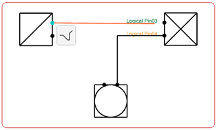
Note: When hovering over a component during the creation of a route, the following information appears:- Unconnected compatible port labels, in green
- Connected compatible port labels, in orange
- Unmapped connection point labels, in red
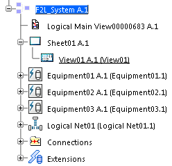
The instance of the net is created in the tree.
The net route is created.
