Generating Automatically Net Diagram Views

You can generate a net diagram view in one click. The generation of the diagram view is based on an existing net system.


Before you begin:
  • Open the net system.
  • In Data Setup, define the symbol representations for the different equipment components.
See Also
Modifying Wiring or Net Diagram View
  1. From the Edition section of the action bar, click Generate Net Diagram .

    Notes:

    The net diagram view is generated. In the following example, Net 1 and Net 2 belong to the NetGroup 1 and Net 3 belongs to NetGroup 2.
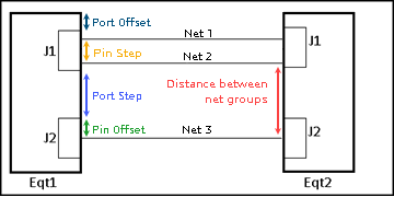
    During the generation, the display of an equipment's connector port is manage as follows:

    • The distance between the net groups is managed by Distance between netgroups options. For more information, see Modifying Wiring or Net Diagram View.
    • The offset of the port is computed as follows: port offset = pin offset = pin step = route width. This value must be defined using the Route Spacing Parameters resource.
    • The port step is computed as follows: Distance between netgroups – 2 x Offset pin.

    Some errors in data may lead to inconsistent diagram generation. If any, these errors are displayed in the Net Generator Error Manager dialog box.

  2. In Net Generator Error Manager dialog box, review the errors. For more information about the errors, see Net Diagram View Generation: Errors.
    The display of error messages stops the generation process except for the Net without parent error. For this error, you can continue the generation of the net diagram view. The net detected in error will not be displayed in the diagram view.