 -
From the Net to Wire section of the action bar,
click Net to Wire CAM.
-
In the Net to Wire Assistant dialog box, define one of the
following elements:
After the selection, the corresponding net or wire system is
automatically retrieved using the implements link.
-
In the Net group node box, select the net group under which the
net definition is stored.
The right pane displays the following information:
- The net group statuses
- The wiring status that indicates if the wiring data complete the net group
connections.
- The route status. It is green if a 3D route can be retrieved through the implement
links chain.
-
Select the input netgroup in the Generate Wiring column.
Note:
By default, the netgroup that is not complete and with a route is
selected.
-
Select the wiring equipment system.
Note:
It is the system where the wiring equipment will be instantiated.
For each net, all connected equipment components are
listed. If an equipment component in the wiring system does not exist, a new
instantiation of the equipment reference is created under the wiring equipment system.
An implement link is created between the equipment on the net system and the equipment
in a wiring system. -
Optional: If the harness data is not complete on the route,
define the location of the following elements:
- Logical Cut's System
- Logical Shunt's System
- Default Wires' System
-
Click
 to generate the wiring
data. to generate the wiring
data.
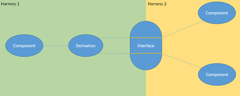
Under the harness logical reference, the following
components are created according to the input graph: Note:
If the logical
reference named after the logical harness does not exist under the wiring reference, it
is created. The father reference is the harness retrieved from the edge.
- A logical harness with the same name as the logical reference.
- For each edge that connects two nodes in the graph, a cable is created.
- One chain of wires is created for each net. Each wire is allocated to the
corresponding net.
The nodes and connections are created in the tree. For more information, see Node Content and Connection. -
Optional: To verify that the net group is complete, click
Net to Wire CAM, and in the Net group node
box, select the net group under which the net definition is stored.
On the right pane, the wiring status of the net group is indicated as
Complete
 .
|