Placing the Relay in Wiring Diagrams

You can place the relay in a diagram view and display its content.


Before you begin:
  • In Me > Preferences > App Preferences > 3D Modeling > Systems Architecture > Electrical Sys. Design > Relay Representation, select the Wiring Representation option in the Relay Type area. For more information, see Native Apps Preferences Guide: Relay Representation.
  • Create and activate a diagram view.
  1. Right-click the relay component and click Place in View.
  2. Click in the diagram view to place the relay.
  3. From the context toolbar, click Display Relay Content .

  4. In the Display Relay Content dialog box, multiselect the content to be displayed and click Yes.

    Tip: You can double-click the contacts or operating devices to select them.

    In the Display in Session and Display in Selection columns, the contacts or operating devices have a Yes status.
    Note: The Display in Session column indicates the display status in the current system. The Display in Selection column indicated the display status in the current relay representation.
  5. In the Step box, type the step value to define the distance between two elements.
  6. In the Offset box, type the offset value to define distance between:
    • the top of the relay and the first element
    • the bottom of the relay and the last element
    The content is placed in the relay.

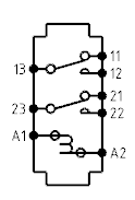
    Note: In this scenario, a text template has been defined and attached to the Default Pin Symbol resource to defined the display of the name of the pins. For more information, see Electrical Logical Resources.