Creating a Table

You can create a table to capture the drawing information in a tabular form using the pointer or the dialog box, with or without selecting a reference. Moreover, you can also insert an attribute link in a table cell.

This task shows you how to:


Before you begin: Open a representation.

Create a Table Using the Pointer

You can create a table quickly using the pointer. In this case, the size of the table is determined by the movement of the pointer.

  1. From the Annotation section of the action bar, click Table .
  2. Click in the sheet to indicate the table anchor point.

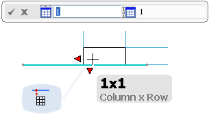
    Four cells are displayed (upper-left, upper-right, lower-left and lower right) highlighted in blue, to help you decide the table orientation.

    The pointer changes to , indicating the position of the first table corner.

  3. Move the pointer in the required direction to decide the table orientation.

    This creates a one-cell table corresponding to one of the four previewed cells.

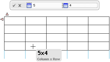
    The table is created according to the direction towards which the pointer is moved. It also displays the table orientation handles in red and the number of columns and rows of the table being created in a tooltip.

    At the same time, a dialog box appears at the top, displaying the number of columns and rows of the previewed table.

    Note: Once you move the mouse in a direction, you cannot change it.
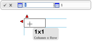


  4. Optional: Select one of the red handles to invert the orientation of the table in the corresponding direction.
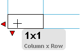

  5. Move the pointer till you get the required number of rows or columns.
    Notes:
    • The graphic area displays some highlighted blue lines to simulate the table with one more row and one more column. This helps you in giving your table its required dimensions.
    • Column and row values are automatically updated in the tooltip as well as in the dialog box whenever the table dimensions are changed with the pointer position.
  6. Click in the sheet to validate the table creation.
    The table is created and placed in the selection mode so that it can be modified or moved.


Create a Table Using a Dialog Box

You can create a table by entering values in a dialog box.

  1. Follow the steps from 1 through 3 mentioned in the earlier scenario.
    At the end of this step, a dialog box appears at the top, displaying the number of columns and rows of the previewed table.
  2. Enter the table dimensions (number of columns and rows respectively) in the dialog box.

    By default, the first value is entered in the column box. You can then enter the required value in the row box.

    You can constrain the table using the dialog box in one or two dimensions.

    • Constraining the table in one dimension:
    1. Enter a value either in the column box or in the row box, to constrain the table either by columns or by rows, respectively.

      For example, enter 5 for the number of columns. This fixes the number of columns of the table. You can no more add a column by moving the pointer in the graphic area and the resultant table has only 5 columns. The number of rows however still changes with the pointer position.


    2. Move the pointer till you get the required number of rows.
    3. Click in the empty space to validate the table creation.
      The table is created.
    • Constraining the table in two dimensions:
    1. Enter the required values in the column and the row boxes, to constrain the table by columns and rows.

      In this case, the table dimensions are no longer manageable through the pointer position. You can however continue modifying the number of columns and rows by entering values till you get the required table dimensions. You can use the column and row boxes several times during the table creation.

    2. Click .
    Note: You can also press Enter or click in the empty space to validate the table creation.

    The table is created and placed in the selection mode so that it can be modified or moved.


Create a Table Using a Reference

You can create a table by selecting a line or another table as a reference. This reference constrains the width or height of the new table depending on the selection.

For our scenario, we are using a line as a reference to create the table.

Before you begin: Create a line.
  1. Click Table .
    The pointer changes to , indicating the position of the first table corner.
  2. Select the line to indicate the table anchor point.

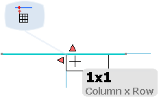
    The reference line is highlighted and four cells are displayed (upper-left, upper-right, lower-left and lower right) highlighted in blue, to help you decide the table orientation.


  3. Move the pointer in the required direction to decide the table orientation.

    This creates a one-cell table corresponding to one of the four previewed cells.

    The table is created according to the direction towards which the pointer is moved. It also displays the table orientation handle in red, the number of columns and rows of the table being created in a tooltip and a context toolbar showing the selected mode of table creation.

    At the same time, a dialog box appears at the top, displaying the number of columns and rows of the previewed table.


  4. Optional: Select one of the red handles to invert the orientation of the table in the corresponding direction.
    Note: The orientation handles are shown depending on the selected reference.


  5. Optional: Use the context toolbar commands to change the table creation mode.
    By default, it creates a table on the nearest extremity.
  6. Optional: Move the pointer over the context toolbar and drag and place it to the required position.
    The pointer changes to allowing you to change the position of the context toolbar as required.
  7. Move the pointer till you get the required number of rows or columns or enter the values in the dialog box to create the table.
  8. Click in the sheet to validate the table creation.
    The table is created.

Insert an Attribute Link in a Table Cell

You can create a link between the text of a table cell and an attribute of a feature.

  1. Create a table using the pointer or by selecting a reference.
  2. Double-click the table to switch it to the edition mode.
  3. Right-click a table cell and select Insert > Insert Attribute Link.
  4. In the Insert Attribute Link dialog box, select the object to which you want the text to be linked to (in the tree, from the 3D space or from the drawing representation).
  5. Select the required attribute and click OK.

    which replaces the cell text's string. If you modify the attribute feature, the attribute link is updated too.