Link an Existing Logical Component (and Create Logical
Reference)
You can create a Logical-Physical Link from a selected
mechanism to an existing logical component by creating a new logical reference
and create the logical-physical mapping in that reference.
Before you begin: A
logical structure must be
present for the product.
-
From the
Behaviors section of the
action bar,
click
Logical and Physical Models Mapping Edition
 . .
The
Logical Mechanical Connection Editor dialog
box appears.
Note:
There is a prefix to the dialog box name indicating the mode.
-
Select the mode:
The mode is indicated by the first part of the dialog box name:
- Kinematic
- Dynamic in
Force
- Dynamic in
Position
-
To go between kinematic (static) mode and dynamic mode:
- If in kinematic
mode, click
Switch Kinematic to Dymamic Mode
 to go to dynamic mode. to go to dynamic mode.
- If in any
dynamic mode, click
Switch Dymamic to Kinematic Mode
 to go to kinematic mode. to go to kinematic mode.
-
To go between the two dynamic modes (driven by force
commands or by position commands):
- If in dynamic
mode driven by force commands, click
Switch Force to Position Command
 to go to dynamic mode driven by position commands. to go to dynamic mode driven by position commands.
- If in dynamic
mode driven by position commands, click
Switch Position to Force Command
 to go to dynamic mode driven by force commands. to go to dynamic mode driven by force commands.
Note:
In the following steps, kinematic mode is used in the
examples.
-
In the
tree,
select the product mechanism.
The following elements appear in the
Logical Mechanical Connection Editor dialog
box:
Note:
If a Logical-Physical Link already exists
for the selected mechanism, it is displayed in the
Mapped Logical box.
-
In the
tree,
select the logical reference that contains the logical reference to connect to.
The selected logical reference appears in the
Selected Logical box.
-
In the
Logical Mechanical Connection Editor dialog
box, click
Create a Logical Component from Mechanism
 . .
The following is the result:
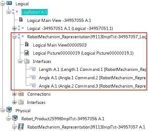
- A logical reference
is created and instantiated under the selected logical reference. In the figure
below the new instance is marked.

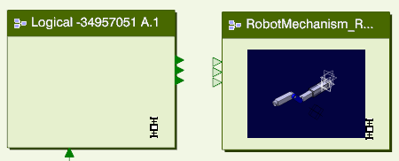
- In the 2D graph, the
corresponding component is added to the logical 2D representation.

- Interfaces are
automatically created on the new logical reference. The logical inputs are
automatically connected to the corresponding mechanical signals. These
connections can be edited, see
Connect or Disconnect a Logical Interface to a Mechanical Signal.
Note:
Outputs are not created by default.
- A logical-physical
link is created, but no corresponding
implement relation.
- The created
logical component appears in
the
Mapped Logical box.
Note:
If physical-logical links are already present for the
selected component, you can select between them in the box.
A logical-physical
link is created from a selected mechanism to a corresponding logical
representation. Mechanical signals are connected to the inputs.
To finalize this connection between a mechanism and the logical
behavior, do the following:
- To use outputs from your
mechanism, create the corresponding logical interface and connect the
mechanical signals. See
Editing Logical-Physical Links.
- To create an implement
relation between the mechanism and the root logical model, corresponding to the
logical-physical link, see
Creating Implement Relations.
- To create
logical connections in the logical layer between the
logical component and the mechanical component, see
Creating Logical Connections.
Link a New Logical Component (and New Logical Reference)
You can create a Logical-Physical Link from a selected
mechanism without having any logical reference selected, by creating a new
logical root interface. The corresponding interfaces are automatically created
on the mechanical reference.
-
Display the
Logical Mechanical Connection Editor dialog
box, select the mode, and select the mechanism to be connected to the logical
layer. See Step 1 - Step 3 above.
-
Click
Create a Logical Component from Mechanism
 in the
Logical Mechanical Connection Editor dialog
box. in the
Logical Mechanical Connection Editor dialog
box.
A logical-physical
link is created from a selected mechanism to an automatically created logical
representation.
To finalize this connection between a mechanism and the logical
behavior, do the following:
- To use outputs from your
mechanism, create the corresponding logical interface and connect the
mechanical signals. See
Editing Logical-Physical Links.
- To create an implement
relation between the mechanism and the root logical model, corresponding to the
logical-physical link, see
Creating Implement Relations.
- To create logical
connections in the logical layer between the logical component and the
mechanical component, see
Creating Logical Connections.
Link an Existing Logical Component (with Logical Reference)
You can create a Logical-Physical Link from a selected
mechanism to an existing logical component directly, without creating a new
logical reference.
Before you begin: The following apply:
-
From the
Behaviors section of the
action bar,
click
Logical and Physical Models Mapping Edition
 . .
The
Logical Mechanical Connection Editor dialog
box appears.
-
Select the mode, see Step 2 in the first task above.
-
In the
tree,
select the product mechanism.
The following elements appear in the
Logical Mechanical Connection Editor dialog
box:
Note:
If a Logical-Physical Link already exists
for the selected mechanism, it is displayed in the
Mapped Logical box.
-
In the
tree,
select the logical reference where you want to create the logical-physical
mapping.
The selected logical reference appears in the
Selected Logical box.
-
In the
Logical Mechanical Connection Editor dialog
box, click
Create a Logical Mechanical Mapping
 . .
The following is the result:
A logical-physical
link is created from a selected mechanism to a selected logical representation.
Mechanical signals are connected to the inputs.
To finalize this connection between a mechanism and the logical
behavior, do the following:
- To use outputs from your
mechanism, create the corresponding logical interface and connect the
mechanical signals. See
Editing Logical-Physical Links.
- To create an implement
relation between the mechanism and the root logical model, corresponding to the
logical-physical link, see
Creating Implement Relations.
- To create logical
connections in the logical layer between the logical component and the
mechanical component, see
Creating Logical Connections.
Remove a Logical-Physical Link
You can remove logical-physical links by removing the
logical-physical mapping.
Note:
Deleting physical or logical objects connected by
logical-physical links does not remove the links; they must be separately
deleted (or rerouted).
-
From the
Behaviors section of the
action bar,
click
Logical and Physical Models Mapping Edition
 . .
The
Logical Mechanical Connection Editor dialog
box appears.
-
Select the mode, see Step 2 in the first task above.
-
Delete the logical-physical link the following way:
-
In the
tree,
select the product that contains the mechanism that is part of the link.
The name of the selected product appears in the
Selected Product box.
-
In the
Selected Mechanism box, select the
mechanism that is part of the link.
-
In the
Mapped Logical box, select the logical
mapping you want to delete.
-
Click
Delete the Logical Mechanical Mapping
 after the
Mapped Logical box. after the
Mapped Logical box.
All mechanical signals are disconnected from the
interfaces. The logical component is now unconnected - the corresponding
logical-physical link is broken.
-
If the link was created by also creating a new logical
reference, delete that logical reference.
-
Delete implement relations.
|

