Creating an Internal Feature | ||||||
|
| |||||
-
From the
Create section of the
action bar,
click
Internal Feature
 .
.
A feature can have one of the following shape definitions: Prism
 ,
Sweep
 ,
Revolve
 ,
Thick Surface
 , or
External Shape
 . For more Information, see
Working with Shape Definitions.
Prism
 is selected as the default shape definition.
Note: You can change the shape definition. The dialog box for the feature changes according to the options offered by the shape.
 -
Select the
profile you want to
extrude.
Tip: If no profile is defined, click Positioned Sketch  to sketch the profile.
- In the Limits tab under First Limit, select the type and enter the required parameters.
- Optional:
Click Mirrored extent
 or under
Second Limit, select the type and enter the required
parameters.

- Optional:
Under Thin Properties (available for prism, sweep, and revolve
shapes) select the Use param for thin feature check box, select a
reference element and enter the required thickness values ().
- Select the Use param for thin feature check box to specify the thin feature parameters.
- From the Reference list, select a reference type.
- Enter the inside and outside thickness values.
This option enables you to add material on both sides of the profile. -
In the
Reference list, select
Neutral Fiber to add material equally to both
sides of the profile.
Important: The Extend across removed faces check box causes a feature not to be confined within the wall of the deleted face of the shelled volume. - Optional:
Click Preview.

- Optional:
In the Draft tab,
- From the Draft behavior list, select Intrinsic to feature.
- Set profile plane as the neutral element and enter the required value to define the draft angle.
- Optional:
In the Fillet tab,
-
Select among the following check boxes and enter the required values,
to fillet the corresponding edges:
- Lateral radius to fillet lateral edges
- First radius to fillet top edges
- Second radius to fillet bottom edges
- Select the Fillet profile ends check box, to fillet the end faces of open sketches.
- Select the Draft fillets check box, to fillet the drafted edges.
-
From the Type list under Intersection
Fillet, select among the following, to create fillets at
required intersections:
- Intersection with Core/Cavity
- Intersection with Core
- Intersection with Cavity
- Select the Fillet radius check box to create fillet by adding material to the feature.
- Select the Round radius check box to create fillet by removing material from the feature.
- Select the Preserve shell thickness check box to maintain the thickness at fillets.
-
Select among the following check boxes and enter the required values,
to fillet the corresponding edges:
-
Click
OK.
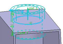
The internal feature is created. Internal Prism.X is added to the tree in the Solid Functional Set.X node.
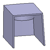
Outside

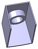
Inside
