-
From the Design section of the action bar, click Bead Function
 . .
The Bead Function Definition dialog box is displayed.
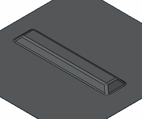
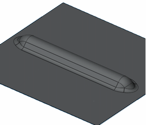
- Select the bead type:
- round bead

- U bead
-
Select the Input Profile.
-
Optional:
Define the Projection direction, i.e. the direction used to project the profile onto the support surface.
If it is not valuated, two default projection modes are available:
- Normal to support: the profile is projected using a normal projection onto the support.
- Normal to profile: if the profile is planar, the projection is computed normally to this plane. If the profile is a sketch, the support plane of the sketch is used for projection.
- Optional: Define the Draft Direction, i.e. the direction for the side faces, which are drafted from the kept part of the support surface.
If it is not valuated, the draft is computed normally to the support surface. - Optional: Define the other parameters:
- Heigth: defines the height between
the support and the top of the create bead
- Radius: defines the radius of the top face of the bead or, for a U Bead (see further), the radius of the fillet between the lateral faces and the top faces.
- Draft angle: defines the angle between the draft direction or the support surface and the lateral faces.
- Length (only for U beads): defines the width of the created shape. measured at the bottom of the bead, on the context.
- Intersection fillet radius: defines the radius of the fillet that if made on the edges between the bead and the context. If no radius is defined, no fillet will be computed.
- End angle: defines the angle between the normal to the context and the end faces.
- End radius: defines the radius of the end face that links the top faces and the end faces.
- Internal intersection fillet: when the input profile is multi-domain, there are edges between the different beads resulting from each domain.

- Click OK to create the bead.
The element (identified as Bead Function) is added to the tree.
|