Adding Leaders and Using Breakpoints | ||||
| ||||
-
Right-click the annotation text and select
Add Leader.
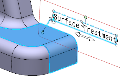
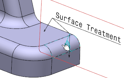
-
To specify the arrow end of a leader, select a geometrical element
as support, for example a face.
- In the case of the 2D leader, you can select the yellow geometrical elements (point, line, or curve) displayed to represent the intersection between the geometrical elements associated with the annotation and the annotation plane.
- In the case of a 3D leader, you can click anywhere in the work area.
- In the case of a 2D or 3D leader, you can select the yellow geometrical elements (point,
line, or curve) to create a 2D leader or click anywhere in the work area to create a 3D leader. Notes:
- In the case of section views, you can choose the extreme point for leader at z=0 or z<0 positions.
- In the case of section cuts, you can choose the section plane (z=0).
The selection allowed is based on the specified preferences. For more information, see Dimension Default Position Along View Normal.
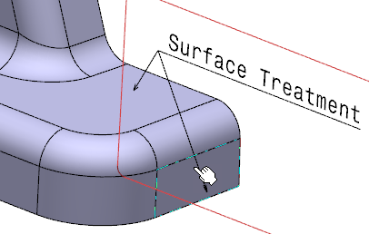
The leader is created and appears in the work area.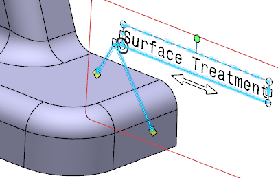
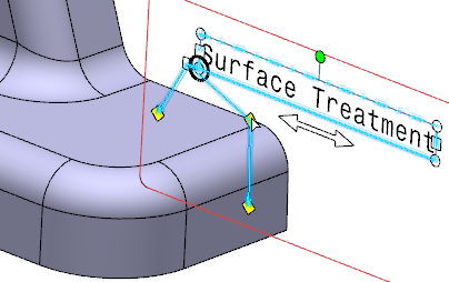
-
To add a breakpoint, right-click the
handle at the extremity of the arrow end and
select
Add a
Breakpoint
.
The breakpoint is identified by as a yellow diamond in the work area.
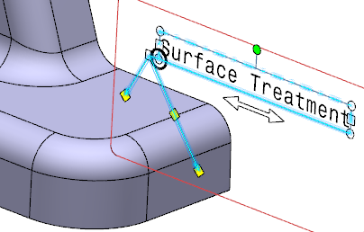
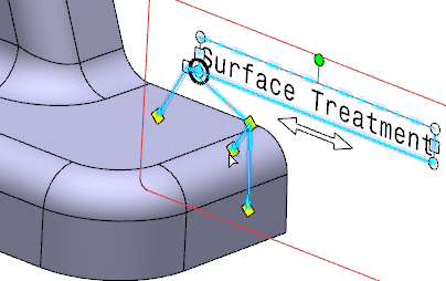
- Optional:
Select the breakpoint in the work area so as to drag the leader as required.
-
To specify the arrow end of a leader, select a geometrical element
as support, for example a face.
The leader is created and appears in the work area.
Notes:- When you add an extremity link, the extremity points cannot be moved but when you move the annotations, the leaders are adjusted accordingly.
- When the breakpoint is added, according to the position of the breakpoint, the leader extremity is adjusted.