Creating an Offset Section View/Section Cut

You can create an offset section view or an offset section cut using a cutting profile as cutting plane. Offset section views/section cuts are specifically aimed at preparing views for 2D extraction.

Offset section views/offset section cuts let you show several features that do not lie in a straight line by offsetting or bending the cutting plane, which is often desirable when sectioning through irregular objects.


Before you begin: Open an existing 3D shape.
  1. From the View Layout section of the action bar, click Offset Section View/Section Cut
    The Offset View Creation dialog box appears.
  2. Select the type of view to create: Section View or Section Cut. For this scenario, select Section Cut.
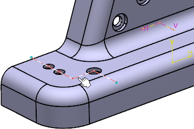
  3. Select or sketch the profile to be used as cutting plane to create a section.

    You can only select a sketch that is valid for the type of view to be created.

    Important:

    You can also click the Sketch to sketch a new profile to use as cutting plane.

    For more information about using this method, you can see Creating an Aligned Section View/Section Cut. The procedure is similar when creating offset section views/section cuts.


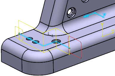
    The offset section cut is previewed. It is made up of two distinct section cut views/annotation planes.

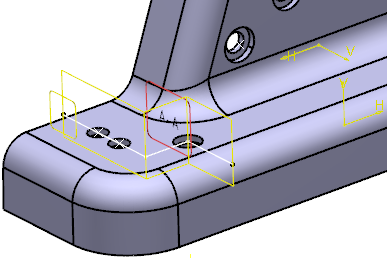
  4. Click Reverse Normal to reverse the normal of the offset section view/cut.

    This reverses the normal of the two section cut views/annotation planes that make up the offset section cut.

  5. Select the Orientation as unfolded check box to change the orientation mode.

    By default, this check box is cleared.

    The FTA view is orientated with an angle. This angle orientation value is equal to the orientation of the first sketch profile line segment with its sketch H axis.

  6. In the Ratio Assistant panel, specify the view ratio.
    • Annotation set ratio: to set the view ratio same as it is specified for annotation set. The value can be in fraction or decimals.

      By default, this option is selected.

    • Current zoom level: to set the ratio according to the current zoom level. The value is in decimals.
    • Suggested ratio: to set the suggested ratio proposed in the list of predefined values based on the current zoom level.

      To customize the list of predefines values, see Ratio Assistant.

      Tip: Select the Propagate to annotation set check box to propagate the specified ratio to the annotation set. When this check box is selected, the specified view ratio is persisted when you open the Ratio Assistant panel.
  7. To change the view ratio, select the view in the 3D area and, on the context toolbar, select Change Ratio.

    You can also right-click the view in the Views and Captures panel and select xxx object > Change Ratio.

  8. Click OK.
    The offset section cut is created and listed in the tree under offset section node (A-A, B-B, and so on) and named as A-A.1, A-A.2, and so on.

    It cannot be activated. Each section cut/annotation plane that makes it up can be activated and behaves like a regular section cut/annotation plane. Each section cut is associative to the sketched line that defines it.


    You can now start creating annotations in each section cut of the offset section cut. If you then extract the view to 2D in the Drafting app, all the annotations defined in each component view are generated.

  9. Optional: Right-click A-A in the tree and select Reverse Normal if you want to reverse the normal of the offset section cut.

    This reverses the normal of all the section cuts/annotation planes that make up the offset section cut.

    Important:
    • The Reverse Normal contextual command is only available if there is no annotation attached to any component view of the offset section view/section cut.
    • You cannot perform the following operations for the component sections views/section cuts of an offset section view/section cut:
      • Delete
      • Reverse Normal
      • Change View Support