Creating Principal Views | |||
| |||
-
From the View Layout section of the action bar
, click
Principal Views
 .
.
You can also select Principal Views
 on the context toolbar.
 - The Principal View dialog box appears. The primary view is
FRONT.
Important: To change the primary view, use the view orientation manipulator arrows.
Depending on which arrow you click the following permutations are applied:
- Right arrow: FRONT > LEFT > REAR > RIGHT > FRONT.
- Left arrow: FRONT > RIGHT > REAR > LEFT > FRONT.
- Up arrow: FRONT > BOTTOM > REAR > TOP > FRONT.
- Down arrow: FRONT > TOP > REAR > BOTTOM > FRONT.
- The Ratio Assistant panel appears.
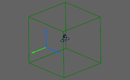
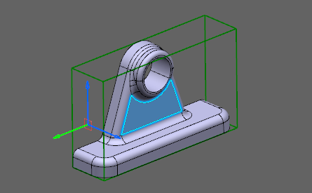
The view bounding box is displayed in the 3D area.

Important: When no reference plane or surface is selected from 3D, then the view bounding box dimensions are computed from the standards, see Layout Views Customization.
- The Principal View dialog box appears. The primary view is
FRONT.
-
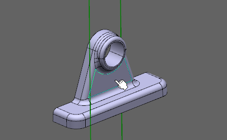
Select a plane to define the FRONT view plane orientation.

Important: When no reference plane or surface is selected from 3D, then the view bounding box dimensions are computed from the standards. The view box is resized according to the 3D model.
Notes:- You can orientate the view bounding box using the view orientation manipulator.
- You can modify the view bounding box angle using the green knob of view orientation manipulator, when you select a reference.
-
In the Ratio Assistant panel, specify the view ratio.
- Annotation set ratio: to set the view ratio same
as it is specified for annotation set. The value can be in fraction or
decimals.
By default, this option is selected.
- Current zoom level: to set the ratio according to the current zoom level. The value is in decimals.
- Suggested ratio: to set the suggested ratio
proposed in the list of predefined values based on the current zoom
level.
To customize the list of predefines values, see Ratio Assistant.
Tip: Select the Propagate to annotation set check box to propagate the specified ratio to the annotation set.
- Annotation set ratio: to set the view ratio same
as it is specified for annotation set. The value can be in fraction or
decimals.
-
In the Principal View dialog box, select the
LEFT and TOP check boxes, and
then click OK.
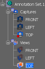
Additional views are displayed in the tree.

Important: - Created view/annotation planes are typed as Projection View/Annotation and their reference planes are the faces of the bounding box.
- Captures are automatically created and associated with the related views. Names are the same for views and captures.
-
To change the view ratio, select the view in the 3D area and, on the context toolbar, select Change Ratio.
You can also right-click the view in the Views and Captures panel and select xxx object > Change Ratio.