About Plot Sectioning | ||
| ||
You can create a cut through a view of the simulation results and then choose whether to display the model on the cut (cross-section), above the cut, below the cut, or both. In addition, you can apply transparency and show or hide edges.
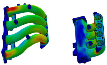
In the example below, a model of a manifold is split into two cut views.
The left view shows the manifold above (in front of) the cutting plane. The right view
shows the cut section and the portion of the manifold below (behind) the cutting plane.

By default, the model is displayed on both sides of the cut. The portion of the model behind the cut is the part that is opposite the normal to the cutting plane as defined by the robot orientation. This portion is displayed using the results contours. You can show the portion in front of the cut as shaded (opaque), as contours (identical to the view behind the cut), or as a wireframe outline. The section through the cut is displayed as contours or symbols, and there is an extra set of internal edges where the cut plane intersects the model. Plot sectioning cuts do not affect the display of vector and tensor arrow symbols in a symbol plot.
You can manipulate plot sectioning cuts using the tools in the context toolbar. For example, you can reverse the cut, show or hide the cutting geometry, show or hide the robot, and change the type of cut (planar, cylindrical, spherical, or iso-contour).
You can create a planar, cylindrical, or spherical cut in two ways. You can specify an origin and normal for the cut, or you can directly select the reference axis and normal direction for the plot section cut. Depending on the model, you can select the following axis options:
- Result axis system (custom coordinate system created in Physics Results Explorer)
- Model axis system (coordinate systems created in one of the model apps)
- SIM axis system (coordinate system inherent in the SIM file and visible from the Display Groups coordinate system entity)
- Global axis system (default coordinate system; indicated by the robot in the 3D area)
A plot sectioning cut remains active for all contour plots until you deactivate it using the controls in the Plot Sectioning context toolbar or the Plot Sectioning dialog box.
Free Body Data
Free body data summarizes the resultant forces and moments at the cut. Free body data is derived from a combination of support types and optionally selected element sets or display groups. Specified element sets connect to the node set or display group support type. You can adjust the orientation of force and moment components so they resolve normal and tangential to the cutting plane, with the coordinate system, or displayed as resultant vectors at each cut position.
When you have multiple cutting levels defined, you can view the free body display at each cut position. The free body definition persists with the Plot Sectioning definition.
Free body forces and moments update during animation sequences and also when you drag the cut plane for the free body to another location.
Iso-value Data
Iso-value type plot section cuts show you cutting surfaces where all the locations on the surface share the same value for the selected field variable. When you first create an iso-value cut, the default cutting surface displays the locations where the current field variable equals a value in the middle of the results range. As you proceed through different steps and frames, the iso-value cutting surfaces adjust to display the locations where the selected iso-value occurs.
You can also change the iso-value to display cutting surfaces for a different value of the current field variable.
In the example below, a displacement contour plot is applied to a bolted pipe joint.

The pipe joint on the left has an iso-value of 0 mm and no cutting surface is
visible. The pipe in the center and on the right show the results when you increase
the iso-value. The cutting surface changes to reflect the adjusted iso-values. In
this example, the higher displacement values are confined to the areas near the bolt
on either side of the pipe.
Named Cuts
You can assign a name to cut surfaces so that you might reference them when creating display groups, sensors, and field expressions. Named cuts associate the cut surface with the specific model selection. For example, you can have a cut surface definition for a fluid flow at a particular location. You can then use a field expression that computes the area integral mass flow to determine the mass flow rate through the named cut surface.
The named cut surface is fixed in space. When you rotate or deform the model, the cut surface location does not change. Named cut surfaces are persistent; that is, you can reference and probe them at any time.
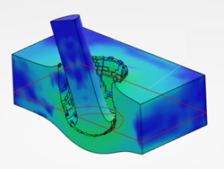
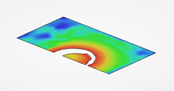
The example below shows a named cut surface for a projectile and plate model over two consecutive frames. From the Display Groups dialog box, you can Highlight the named cut surface. As the projectile travels through the plate, the location of the named cut surface does not change. Therefore, the visible geometry changes on a frame-by-frame basis. Results might or might not be visible depending on whether the geometry of the model intersects the named cut surface for a given frame.
| Projectile and Plate (Whole model view) | Named Cut Surface (View Section) |
|---|---|
 |
 |
 |
 |