Partitioning the Design Space

You can identify functional regions that remain frozen during the conceptual shape exploration.

This task shows you how to:


Before you begin:
  • As partitioning may introduce non manifold topology, it is recommended to copy and paste the body as result with link. Hide the initial body and define the pasted body as the in work object.
  • Create a design space. For more information, see Selecting Parts for the Topology Optimization.
  • Apply a material.

You can partition a volume using a body, a surfacic feature, or one or more faces of the body.

Preserve Faces Using an Automatic Offset and an Extrapolation

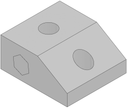
You can partition a volume by selecting one or more faces and an offset value to preserve the selected faces inside the partition result.

  1. From the Design Study section of the action bar, click Partition Design Space .

    If the active object is not a 3D shape, select the body to partition in the dialog box that appears.

    In Me > Preferences, if the Use copy with link for reference design partition option is selected, the reference design is copied in another body.

  2. In the Partition Design Space dialog box, select Preserve faces by offset.
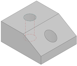
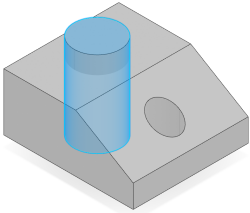
  3. Select one or more faces.


  4. Optional: Select the volume to partition.
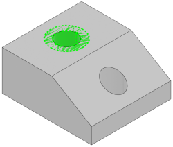
  5. Define the offset value.
    The cutting volume is highlighted in green.
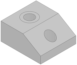
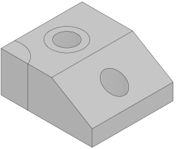
  6. Define the extrapolation mode:
    • Up to next
    • Dimension
  7. Click OK.


    Note: When multiple faces are selected, whether they are connected or not, a single offset is generated:
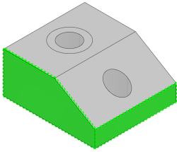
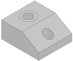
Split by Another Body

You can partition a volume using a cutting body.

  1. From the Design Space section of the action bar, click Partition Design Space .
  2. In the Partition Design Space dialog box, select the splitting body.


  3. Optional: Select the volume to partition.
  4. Click OK.


Split by a Surfacic Element

You can partition a volume using a surfacic feature.

  1. From the Design Space section of the action bar, click Partition Design Space .
  2. In the Partition Design Space dialog box, select the surfacic feature as the splitting element.


  3. Optional: Select the volume to partition.
  4. Click OK.


    Note: You can right-click a cutting element in the list and use stacked commands to create geometry on the fly.

Advanced Partitioning

If you need to apply a load or a boundary condition on a specific area of your design, you can use the Sew command to prepare your model correctly.

Before you begin: Create or insert the sew features before the partition features in the tree.
  1. From the Design Space section of the action bar, click Sew Surface .
  2. Select the object to sew.

    It must lie on the body.


  3. Define the orientation.
  4. In the Sew Surface Definition dialog box, clear Simplify geometry.
  5. From the Design Space section of the action bar, click Partition Design Space .
  6. In the Partition Design Space dialog box, select a body, a surfacic feature, or one or more faces of the body.
  7. Click OK.
    The body is partitioned and the sew surface can be selected as a support for a load or a boundary condition.

    Notes:
    • The sub-volume has been selected as a functional region.
    • A pressure can be applied on the specific area that was sewed on the design space:

When you edit a partition, transparency is applied to the functional regions, unless a material is applied.