About the Graphical Properties of Generated Geometry | ||||
|
| |||
General Mechanism
This sub-topic introduces the general mechanism that governs the modification of the graphical properties of generated geometry.
First of all, remember that several elements are taken into account to define the graphical properties of generative views, according to a precise priority order. Some apply at view creation, some apply once a view has been created. This enables you to comply with the chosen standard, while answering your corporate or individual configuration needs. See About View Creation and About View Content Configuration for more information.
When these general definitions are not enough, you can modify yourself the graphical properties of generated geometry in a view generated from a 3D representation, element by element. This enables you to get a configured result.
Graphical properties include show, layer, symbol, color, line type, line thickness. These modifications are performed through the Properties dialog box. These graphical properties and hide/show property are all volatile properties. They have to be persisted at update.
| Important: You can change the graphical properties of generated geometry in exact and approximate views only. |
Persistency at Update
This sub-topic explains what you need to know when updating a view after having changed the graphical properties of some of its generated geometry.
Each time a view is updated, generated geometry is deleted and recreated. Depending on your configuration, the modifications of the graphical properties of generated geometry (or the deletion of these elements) may or may not be persistent at update. This means that these modifications or deletion may or may not be kept when updating the view later on.
| Important: Graphic dress-up properties of generated items for a view which is locked or not up-to-date will not be persistent. |
You can specify whether or not you want to preserve these modifications during the view update, you have two different ways:
- Through the view options in section, under Generated Geometry, selecting the Preserve modifications applied to graphical properties check box.
- Using Preserve
modifications applied to graphical properties
 from the View Layout section of the action bar.
On the other hand, you can restore the original properties and/or deleted elements in a view using the Restoring Original Properties and Deleted Elements.
Since generated geometry is deleted and recreated each time the view is updated, when edited, the graphical properties of the geometry is stored according to the 3D origin of the geometry. This way, the right properties are applied to each new geometry according to its 3D origin. Thus, once updated, generated geometry inherits the graphical properties corresponding to the 3D origin previously stored.
The persistency of this graphical dress-up/delete:
- Is available in exact and approximate views. In views other than exact and approximate (CGR or Raster), an update operation will reset the elements to their original properties.
- Creates additional specifications in the drawing, which increases the file size and requires additional computing during the update process.
- Is available for drawings extracted from CATProcess in DELMIA apps. The following graphical properties can be changed: linetype, line thickness, color, point symbol, layer, show/no show or deleting a generated item.
Associative dress-up features can be created by selecting the Preserve modifications applied to graphical properties
 check box through
section, under Generated Geometry.
check box through
section, under Generated Geometry.To restore all the associative graphical dress-up properties, 3D properties and deleted elements in a view use the Restoring Original Properties and Deleted Elements command.
Changes in the graphical properties of the following generated elements will not be preserved after an update:
- Hatching patterns (in sections and breakout views)
- Edges corresponding to symbolic visualization of fillets
- Edges representing limits of detail, quick detail or section views
- Edges representing profiles of 3D clipping or broken views
- Bend limits in unfolded views of sheet metal parts
- Annotations generated from 3D annotations or 3D elements (structure, piping)
Particular Cases
This sub-topic introduces a few particular cases that you need to be aware of when changing the graphical properties of generated geometry.
Case of Geometrical Elements on Cylindrical Faces
This section provides specific information that apply when changing the graphical properties of generated geometry on views generated from cylindrical faces.
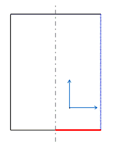
In the following example, the graphical properties of two elements on a generated view are modified.
3D part #1:

The graphical properties of two generated elements are modified in the view:
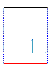
After the view is updated, the modified graphical properties are propagated to generated elements with the same 3D origin as the modified elements:
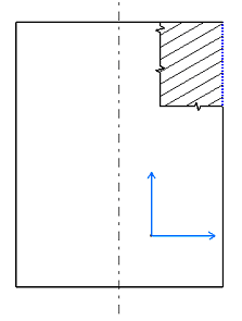
3D part #2:

The graphical properties of a generated element are modified in the view:
After the view is updated, the modified graphical properties are propagated to generated elements with the same 3D origin:

Case of Geometrical Elements on Intersecting Planes
This section provides specific information that apply when changing the color of generated geometry that belongs to intersecting planes.
When you update a generated view you have modified, the colors are re-generated with the geometrical information from the part, and you might obtain unexpected results. Take the following part as an example:

On the generated view, the color of line a is modified:
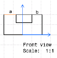
After the view is updated, both lines a and b are red:
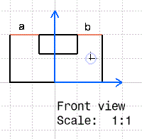
The reason is that the view is refreshed with the part information and lines a and b are considered as the intersection of two planes and not as two different geometrical elements of the generated view.
Handling Layers
This sub-topic explains how to handle layers when changing the graphical properties of some generated geometry.
When you select a layer and modify the graphical properties of some elements, the properties will be applied only when you update the selected layer. By default, the view and its elements are created in the layer None, as displayed in the Graphic Properties in the Object Properties panel. Yet, if you modify your view and add elements, they will be created in the current layer, which can be layer 0, 1, 2 or any layer you select in the toolbar.
Each time a view is updated, generated geometry is deleted and recreated. As a result, generated geometry for which no layer is explicitly specified (which is set to the layer None), is placed into the current layer (that is, the layer which is selected in the Graphic Properties when the view is updated). Therefore, to avoid unexpected results, it is recommended to set the current layer to None before updating a view.
Miscellaneous
This sub-topic provides miscellaneous information about the graphical properties of generated geometry.
If the projection of an element is hidden due to overlapping components, its graphical properties are retained. When the element is visible again, it is displayed with the same graphical properties and not the default ones.