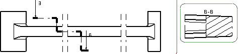
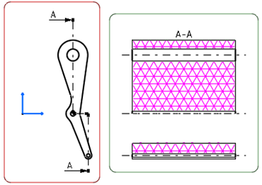
Create an Offset Section View/Cut
You can create an offset section view or an offset section cut using a cutting profile as cutting plane.
-
From the
View Layout
section of the
action bar,
click
Offset Section
View
 or
Offset Section
Cut
or
Offset Section
Cut
 .
.
- In the Tools Palette, only the offset constraint is available for selection.
- In the
Creation Options panel, you can select the graphic
properties and the operator specifications that you can propagate to this view
from its reference view. If the
Disable generative view style usage check box is
cleared in
Me
 > Preferences > App Preferences > 3D Modeling > Mechanical Systems
tab, then you can also apply the available generative view styles to this view.
For more information, see
Creating a View using Generative View Styles.
> Preferences > App Preferences > 3D Modeling > Mechanical Systems
tab, then you can also apply the available generative view styles to this view.
For more information, see
Creating a View using Generative View Styles.
-
To specify the direction of the profile, select one of the following valid
reference elements:
- A generated, such as an edge, a centerline, or an axis line. In this case, the constraint is associative to the referenced 3D geometry.
- A generated circle. In this case, the constraints are associative to the 3D.
- One of the coordinates axis of the sheet. In this case, the constraint is not associative to the 3D.
- A sketched line. In this case, the constraint is not associative to the 3D.
Tips: - Selecting a constraint keeps the Tools Palette hidden, until the second point of the current line is not created.
- The selected constraint is not applied if you select the reference element either as a 2D point (in this case, the profile segment goes through this point), or a 2D circle (in this case, the coincidence constraint is applied and the profile segment goes through the center of this 2D circle).
- If you are not satisfied with the profile you created, you can,
at any time, use Undo
 or
Redo
or
Redo
 .
Note that Smartpick assists you when creating this profile. For
more information, see Sketcher User's Guide: Using
Smartpick.
.
Note that Smartpick assists you when creating this profile. For
more information, see Sketcher User's Guide: Using
Smartpick. - Once the profile is created, the constraints associated can be deleted in the edit mode but cannot be modified nor recreated unless you recreate the whole profile.
- In case the 3D geometry to which the profile is associative is deleted, the profile is still available, but is not associative and the constraint is shown in the edit mode.
- In case the section view is isolated, all the profile constraints are lost.
- You can select a cylindrical surface, which is projected as a 2D edge, as the reference element for applying a section constraint. In this case, the constraint is always applied to the axis of the selected cylindrical surface.
The section plane appears on the 3D part and moves dynamically on the part.
-
Double-click in the sheet to end the
cutting profile creation.
When creating an offset section view, remember that positioning the section view using the cursor defines the section view direction. The cutting profile is associative to the hole.
Click in the sheet to define the section cut direction and position the view.
-
Click in the sheet to define the section cut direction and
position the view.
-
Right-click the callout and select
Properties. Under the
Callout tab, modify the required callout
properties.
Notes:- The frame of the active view adapts to the length of the cutting profile.
- You can assign a line type to the view to be generated.
For this, go to
Me
> Preferences > App Preferences > 3D Modeling > Mechanical Systems
section,
click
Configure next to
View Linetype and select the
required options from the dialog box.
- There is no associativity for .model files.
- You can also create a wavy section edge when the profile of the offset section cut/view
ends inside the geometry. For more information, see Wavy Edges.
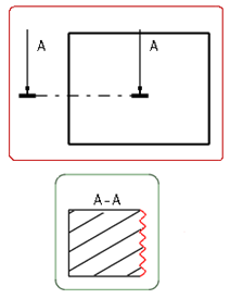
- Wavy edges are not supported in shaded background mode.