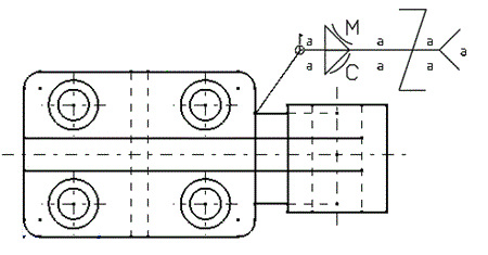
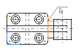
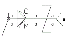
-
From the Annotation section of the action bar, click Welding Symbol
 . .
-
Select one or two elements defining the weld to determine the position of the
leader anchor point.
-
Move the pointer to position the symbol or you can snap the leader orientation
on one of the privileged directions, and position the symbol.
The leader segment turns to cyan color, indicating
the snapping on the privileged direction. Note:
If the leader is associated to
two line references, it can be snapped on the horizontal and vertical
directions, and also on the angle bisector line direction between the two
line references. In this case, a positional link is created between the
leader and the two line references.
-
In the Welding Symbol dialog box, select the direction
for the Weld text side
 and the
Indent line side and the
Indent line side
 . .
- Enter the values in the required boxes.
Notes:
- When you specify the size of weld and length of weld, a new box
appears above it for additional information.
- The engineering symbols can be inserted in all the boxes except the
box below plug symbol.
- Select the required weld symbol,
complementary symbol and finish symbol.
Notes:
- The weld symbols are available depending on the selected
standard.
- When an elementary or a supplementary symbol is selected, another
pair of these symbols appear above them.
- When the plug weld symbol is selected, a box appears below it.
- The staggered (Z) symbol is displayed in the welding symbol
annotation only if a text is entered next to the staggered
symbol.
- In the Welding Symbol dialog box, the staggered
symbol appears based on the welding staggered display parameter
selected in the Standard definition dialog box.
For more information, see Welding.
- Usual: To display the staggered (Z)
symbol in the welding symbol annotation.
- Alternative: To offset the weld
symbol on the opposite side of the reference line. Click the
Alternative welding staggered
display
 to activate the alternative welding staggered
symbol. to activate the alternative welding staggered
symbol.
- Optional:
Add complementary indications like a field weld, weld-all-around, or a weld
tail.
- Optional:
Click Import file to import a text file.
- Optional:
Click Reset to clear all the values.
-
Click OK.
The welding symbol is created.

Note:
The values entered in the dialog box are saved as user preference for next
usage.
-
Optional: Modify the welding symbol position by dragging it to the
required location.
-
Double-click the welding symbol to edit it. For example, click the weld text
side to change the side of the text.
|
 .
.

 and the
Indent line side
 .
.
 is available only when the welding symbol
System-A is selected in the welding
parameters of ISO standard.
 to activate the alternative welding staggered
symbol.
