- Name
- Name of the selected dataset displayed in the tree.
|
- Selectable
- If this option is cleared, you cannot select the
dataset in the 3D.
|
- Color
- Defines the color of the selected dataset.
|
- Opacity
- Defines the transparency of the selected dataset, from transparent to
solid.
|
- Factor
- Defines the opacity factor.
|
- Blending
-
| Type
|
Representation
|
| occluded
|
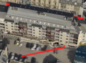
|
| overlay
|
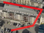
|
| dual
|
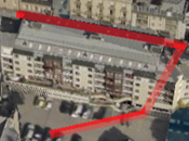
|
|
- Type
- Types for simple features with points:
| Type |
Representation |
| Billboard
|

|
| Disc
|

|
| Tube
|

|
| Sphere
|

|
| Pyramid
|

|
- Types for polygonal areas:
| Type
|
Representation
|
| filled
|
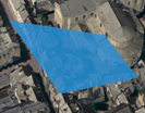
|
| line
|

|
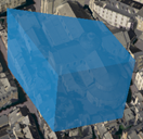
| extruded
|
|
|
- Line Pattern
- Lets you define a pattern for simple features with lines:
| Pattern
|
Representation
|
| solid
|

|
| dash
|

|
| dot
|

|
| dash/dot |
 |
|
- Line Width
- Defines the line width for lines and polygonal areas.
|
- Polygon Stroke
- Lets you define styling attributes for simple features with
polygons. To do so, select the box then set the following parameters:
- Color lets you specify the stroke
color.
- Opacity lets you specify how
transparent the stroke is.
- Width lets you specify how thick the
stroke is.
- Pattern lets you choose a pattern
for the polygon stroke:
| Pattern
|
Representation
|
| solid
|

|
| dash
|

|
| dot
|

|
| dash/dot |
 |
|
- Extrusion Height
- Defines the extrusion height for polygonal areas.
This attribute is relevant when the
extruded type has been selected.
|
- Elevation Mode
- Lets you adjust the vertical positioning of a dataset by specifying an offset.
Note:
This
capability is not available for tiled specific buildings.
| Mode |
Description |
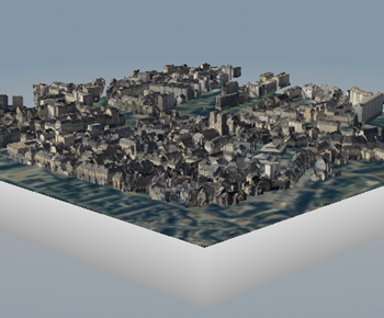
| geometry
|
Elevation is set according to the vertical
(Z) coordinate value.
|
| ground
|
Elevation is set from the Earth's surface.
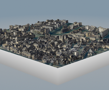
- For point data (element, model, trees, POIs),
each point is set from the Earth’s surface.
- For line data, each point belonging to the line
is set from the Earth’s surface.
- For the polygon data, the first point is set
from the Earth’s surface, and the same elevation
is applied to the other points.
Note:
There might be an impact on visualization.
|
| advanced
|
Elevation is set according to the selected
attribute. After selecting
advanced, click  to define your mapping. See
Use Mapping
Method for more information. to define your mapping. See
Use Mapping
Method for more information.
|
|
- Elevation Offset
- Defines the offset value to be added to the elevation value.
|
- Anchor
- Displays or hides the anchor for simple features with points.
| Anchor OFF
|
Anchor ON
|

|

|
|
- Vertices
- Defines the number of vertices for simple features with points.
| Vertices = 4
|
Vertices = 8
|

|

|
|
- Dynamic Update
-
|
- Min Level
- Minimum subdivision level of the quadtree defined when
creating the dataset.
|
- Max Level
- Maximum subdivision level of the quadtree defined when
creating the dataset.
|
- Bounding Box
- Displays the associated CRS and the coordinates of the
left lower and right upper corners in the given projection.
|