Select the
No trim
check box if you do not want the base surface to be modified.
Select the
Trim
check box to trim the base surface at the connecting edge of the mating flange.
Select the
Trim and Split
check box to trim the base surface at the connecting edge of the mating flange and additionally split it
using the reference element as the cutting element. A Split
feature
is created and aggregated under the Mating Flange feature in the
tree.
No trim
Trim
Trim and Split
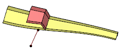
Reverse Direction
Click
Reverse Direction
to inverse the thickness direction, according to the orientation of the reference element.
As a result, the mating shape is displayed on the other side of the base surface.
Original direction
Reversed direction
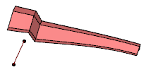
Flip Flange
Click
Flip Flange
to inverse the mating flange direction, according to its orientation. As a consequence, the mating shape is
displayed on the other side of the reference location.
Original orientation
Inversed orientation
Warning:
The
Flip Flange
button is only available if the
Both sides
check box is cleared.
Both Sides
Select the
Both sides
check box to create a both side mating flange using a second reference element. By default, the same selection is used for both first and second reference element and direction.
Both side mating flange with one reference element
With a second reference element
The second reference location is aggregated under the Mating Flange feature and can be used as an input
for a further operation.
The
Linked directions
check box is automatically selected if the
Both sides
check box is selected. For both sides is used the first
Reference direction.
The second
Reference direction
text box is disabled.
Clear the
Linked directions
check box to enable the second
Reference direction
text box and select another reference direction for the second side.
With a second reference element and modified direction
Tip:
To be able to use
Trim and Split
option with
Both Sides, the reference elements must be different. In this case,
the portion between the two elements is kept.
Deviation
Using the
Deviation
option in the
Mating Flange
dialog box, you can specify an individual deviation
value.
This can be needed, for example, if unwanted tiny edges are created because the
default deviation tolerance is too small. In these cases, you can increase the deviation value until the tiny edges
are removed.
By default, the deviation tolerance set in the
Maximum Deviation
text box in
Me > Preferences > App Preferences > 3D Modeling > 3D Modeling Core> Generative Shape Design, Generaltab, Tolerant Modeling section,
is used.
Tiny edge created with a swept surface as input element
Tiny edge removed by increasing deviation
Notes:
The status of the
Deviation
check box depends on the
Continuity Type
defined in
Me > Preferences > App Preferences > 3D Modeling > 3D Modeling Core> Generative Shape Design, Generaltab, Tolerant Modeling section. It is set as None if no continuity type is selected.


 > Preferences > App Preferences > 3D Modeling > 3D Modeling Core
> Generative Shape Design, General tab, Tolerant Modeling section,
is used.
> Preferences > App Preferences > 3D Modeling > 3D Modeling Core
> Generative Shape Design, General tab, Tolerant Modeling section,
is used.
