Developing Modes
There are three developing modes. The difference between these three modes deals with the way the points are mapped onto the revolution surface.
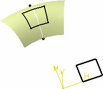
The following illustration shows the three developing types, based
on developing the black solid wire, the two black dotted wires
representing the 1 and 2 coordinate lengths in the wire's
axis-system.

As you can see, the results differ slightly, the developed curves not ending on the same point.
Develop-Develop
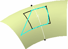
A given point (p) of the wire is developed on the revolution surface by mapping its first coordinate as a curvilinear abscissa on the revolution surface (1 into 1') up to a (p') point (represented by the light blue dotted curve), then from that (p') point reporting the other coordinate of (p) as a curvilinear abscissa (2 into 2') along the revolution surface (dark blue dotted curve). The resulting developed wire is the dark blue solid curve in the above illustration.
Develop-Project
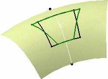
A given point (p) of the wire is developed on the revolution surface by mapping its first coordinate as a curvilinear abscissa (1 into 1') onto a virtual cylinder passing through the point on support (default or user-defined), to generate a (p') point (represented by the light blue dotted curve), reporting the other coordinate parallel to the cylinder's revolution axis, then projecting normally from that cylinder onto the revolution surface (light green dotted line). The resulting developed wire is the light green solid curve in the above illustration.
Develop-Develop reversed
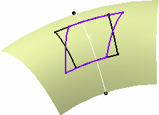
A given point (p) of the wire is developed along the revolution surface by mapping its first coordinate as a curvilinear abscissa on the virtual cylinder up to a (p'') point (represented by the pink dotted line), then from that (p'') point reporting the other coordinate of (p) as a curvilinear abscissa along the revolution surface. The resulting developed wire is the pink solid curve in the above illustration.
