-
Click Develop
 from the Morphing section in the Generative Shape Morphing
app or from the Develop section in the Generative Shape Develop
app. from the Morphing section in the Generative Shape Morphing
app or from the Develop section in the Generative Shape Develop
app.
- In the Wire to develop box, select the wire(s) to be developed.
- By default, the plane containing this wire is automatically computed. If a wire to develop is replaced using the Replace button, the new wire must lie on the same plane as the wire to be replaced. If it lies on another plane, use the Remove button or clear the selection and select a new wire.
- However, when the wire is a line, you need to specify a Wire plane.

- In the Support surface box, select the surface onto which the wire is to
be developed.
- Click Preview.
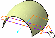
The axis-systems are displayed both on the wire's
virtual plane and the surface. These are the default axis-systems. By
default, the origin of the support's axis-system is located at a
point on the surface where the plane is parallel to the wire's plane. However, it is usually more pertinent to specify
exactly the axis-systems origin.

- Click the Point box and select a point, on
the surface, defining the support axis-system's origin.
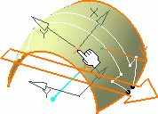
The axis-systems are modified, the support's
axis-system to coincide with the selected point, and the wire's
axis-system to retain the shortest distance between the two
axis-systems' origins. Consequently, the resulting wire is also modified.

-
If you select the Position 2D wire check box, click
Show Parameters to modify the wire axis-system's
positioning.
Note:
The wire's axis-system turns green, meaning it can be edited,
i.e. change location. You can directly move it in the geometry and the
dialog box will be updated accordingly.
- Specify the wire axis-system's origin by either entering coordinates, or
selecting a point.
- Specify the x-axis of the axis-system by either selecting a line or
specifying a rotation angle in relation to the initial lowlight
position.
- Select the X-axis reversed check box to invert
the x-axis orientation (while keeping the y-axis unchanged).
- Select the Y-axis reversed check box to invert
the x-axis orientation (while keeping the y-axis unchanged).
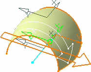
You could get something like this:

Note:
If you want to go back to the initial axis-system positioning,
clear the Position 2D wire check box and collapse the
dialog box using the Hide parameters button.
- Click OK to create the developed wire.
|