Creating a Variable Draft Angle | |||||
|
| ||||
-
From the Volume section of the action bar, click Draft Variable
Angle
 .
.
Tip: As an alternative, you can click Draft Angle  , then click Variable
available in the dialog box.
, then click Variable
available in the dialog box. The Draft Definition dialog box appears, displaying the variable angle draft option as activated. If you click the icon to the left, you then access the command for performing basic drafts.
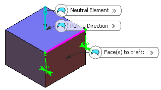
- In the Neutral Element box, select a surface or plane or a face.An arrow appears on the 3D shape, indicating the default pulling direction. The app detects two vertices and displays two identical angle values.
The Support box is filled with the volume owning the selected face.
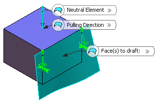
- Click Preview to see the draft to be created:

- For the new point, enter a new angle value.
The new radius value is displayed.
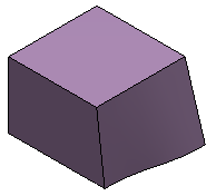
- Click OK to confirm the operation.The element (identified as Draft.xxx) is added to the tree.
For more information, see 3D Modeling: 3D Modeling Core: Part Design User's Guide: Creating Basic Drafts or Creating Drafts with Parting Elements.