Blood Flow Model | ||
| ||
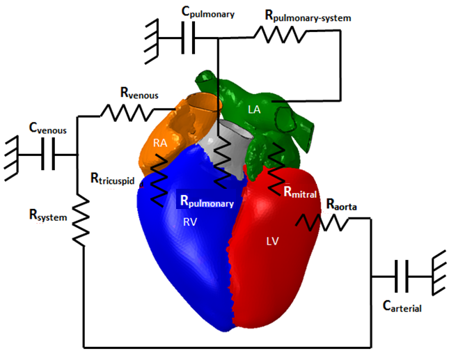
The circuit shown in the figure below is a schematic representation of
the blood flow model. Resistors represent flow resistances and capacitors
represent structural compliances.
The blood flow model uses the approach described in Pilla et al.; however, Pilla et al. use a lumped parameter representation for all components, whereas the Heart Model uses a hybrid approach involving both lumped parameter and 3D representations. In particular, the parameters associated with compliance and contractility of the four heart chambers in Pilla et al. have been replaced by a 3D finite element representation.
The compliance and contractility of the heart within the blood flow model are incorporated into the mechanical simulation through the fluid cavities shown in the table below.
| Part Name | 3DX Model Feature Name | Reference Point | Surfaces |
|---|---|---|---|
| Aortic_Arch A.1 | Fluid_Cavity_AA | CAV_RP_AA | AA_Interior_Face and hole meshes |
| Left_Atrium A.1 | Fluid_Cavity_LA | CAV_RP_LA | LA_Interior_Face and hole meshes |
| Ventricles A.1 | Fluid_Cavity_LV | CAV_RP_LV | Ventricles_LV_Interior_Face and hole meshes |
| Pulmonary_Trunk A.1 | Fluid_Cavity_PT | CAV_RP_PT | AA_Interior_Face and hole meshes |
| Right_Atrium A.1 | Fluid_Cavity_RA | CAV_RP_RA | RA_Interior_Face and hole meshes |
| Ventricles A.1 | Fluid_Cavity_RV | CAV_RP_RV | Ventricles_RV_Interior_Face and hole meshes |
| Superior_Vena_Cava A.1 | Fluid_Cavity_SVC | CAV_RP_SVC | SVC_Interior_Face and hole meshes |
| Compliance A.1 | Fluid_Cavity_AC | CAV_RP_C | Mechanical_Surface_Mesh_AC (surface mesh) |
| Compliance A.1 | Fluid_Cavity_PC | CAV_RP_C | Mechanical_Surface_Mesh_PC (surface mesh) |
| Compliance A.1 | Fluid_Cavity_VC | CAV_RP_C | Mechanical_Surface_Mesh_VC (surface mesh) |
The last three cavities shown in the table above are defined as cubic volumes and used to model the compliance of the arterial, venous, and pulmonary circulation systems. Initial dimensions of each cavity are chosen to establish a total blood circulation volume of 5 liters. Each cavity is attached to a grounded spring with a stiffness tuned to provide the appropriate pressure-volume response (that is, compliance) for that cavity.
Blood flow between the hydrostatic fluid cavities is modeled using the fluid exchange definitions shown in the table below. Each fluid exchange link possesses a viscous resistance coefficient tuned to obtain atrial and ventricular pressures according to published normal ranges shown in the table in Summary of Simulation Results.
| 3DEXPERIENCE Feature Name | Description | First Chamber | Second Chamber |
|---|---|---|---|
| LINK_AC-VC_Body_Resistance | Extra-cardiac resistance | Fluid_Cavity_AC | Fluid_Cavity_VC |
| LINK_VC-RA_Venous_Resistance | Venous resistance | Fluid_Cavity_VC | Fluid_Cavity_RA |
| LINK_RA-RV_Tricuspid_Valve | Tricuspid valve resistance | Fluid_Cavity_RA | Fluid_Cavity_RV |
| LINK_RV_PCPulmonary_Valve | Pulmonary valve resistance | Fluid_Cavity_RV | Fluid_Cavity_PC |
| LINK_PC-LA_Pulmonary_Resistance | Pulmonary resistance | Fluid_Cavity_PC | Fluid_Cavity_LA |
| LINK_LA-LV_Mitral_Valve | Mitral valve resistance | Fluid_Cavity_LA | Fluid_Cavity_LV |
| LINK_LV-AC_Aortic_Valve | Aortic valve resistance | Fluid_Cavity_VCLV | Fluid_Cavity_AC |
Reference values for blood density and bulk modulus are taken from Mourad and Kargl as 1.027 × 10⁻⁹ tonne/mm3 and 2.4 MPa, respectively. However, the bulk modulus is reduced by a factor of 1000 to increase the stable time increment and thus reduce run time. The reduced stiffness has a negligible effect on the results as the fluid is still significantly stiffer than the muscle in compression.