Cardiac Tissue Fiber Orientations | ||
| ||
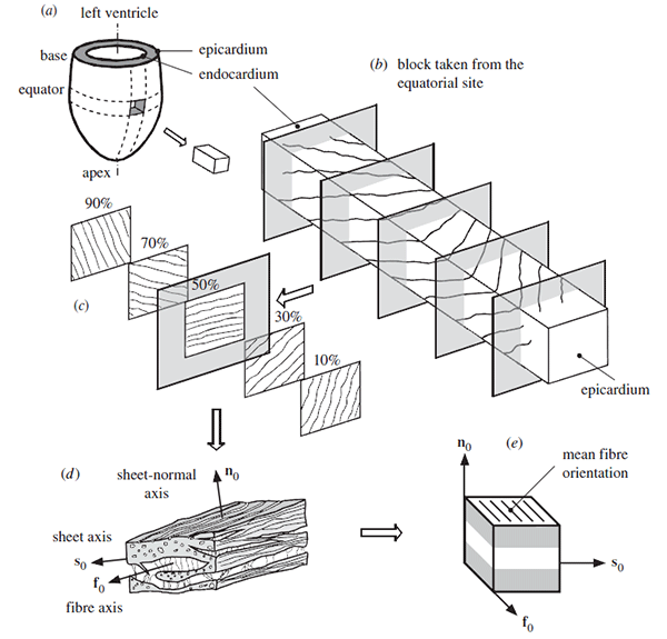
As shown in the figure below from Holzapfel and Ogden, the fiber orientations associated with the structures in the heart are complex due to:
- The complex organic geometry of the heart
- Orientations changing across the surface of the heart
- Orientations changing through the thickness of the heart wall
Local material orientations are not defined in Mechanical Scenario Creation for the atria, ventricles, SVC, aortic arch, and pulmonary trunk. However, the orientations are defined as discrete fields in the Abaqus input files that are generated by the simulation process.
This methodology requires that a separate orientation be defined at the centroid of each element. The fiber angles, in the ventricles are approximately equal to –60° on the epicardium and +60° on the endocardium as shown in Streeter et al., which is consistent with Genet et al. The fiber orientations in the atria (as well as the superior vena cava (SVC), aortic arch, and pulmonary trunk) were approximated using Figure 20 in the euHeart Final Project Report. The model includes three Discrete Field definitions.
After running the analysis, you can visualize the
fiber orientation (as shown in the figure below) by examining the results with
Physics Results Explorer.
From the
Plots section of the
action bar,
click
Create Symbol Plot, then select
ORIENT (at element integration point) for the
stress components variable.

A simulation process is provided to redefine the initial fiber orientations for the atria, ventricles, or any portion thereof, as a result of any modifications you make to the model geometry; for example, after creating a partition in the ventricle that is then remeshed. For more information, see Remeshing and Matching Meshes.