Type of Representation
Before creating a route or a branch, you need to select one of the options available in
Me  > Preferences > App Preferences > 3D Modeling
to define the type of representation.
> Preferences > App Preferences > 3D Modeling
to define the type of representation.
Type of RepresentationBefore creating a route or a branch, you need to select one of the options available in
Me Directional PointThis section describes the directional point behavior. When you start creating a route from a port, a directional point If you bend the route directly after the directional point, a computed node The offset of the computed node is calculated so as to keep the straight distance between the reference point of the port and the directional point. The computed node is displayed in the Node edit table dialog box with the same inner bend radius as the directional point but is not editable. The length between the port and the directional point is managed through the Directional Length table. For more information, see Directional Length. Each time a directional point is created or modified, use the Directional Length table to
retrieve the right value to apply. If only one matching value is found, this value
is automatically applied to create the directional point. If several matching values
are found, the Directional Length Table appears to let you
choose a value to create the directional point. Make sure you have selected
Maintain Straight Route from Port in Me The following commands are impacted:
Route InformationYou can verify the route properties using the Route Information command. To verify the route properties, double-click the route and click HVAC duct information that appears on the right side of the work area. The first part of the dialog box shows the line ID information. If the duct is not linked to the line ID, then these lines do not appear. The second part the dialog box shows the duct information, such as equivalent diameter, end style, thickness, directional length, etc. The third part gives information about the length and the rotation of angles. These attributes are displayed in the dialog box only when you edit the duct. If the standard and equivalent diameter are different, insert an additional naming: LineID and Route for duct. Note:
You can click
Node Table
Minimum Straight LengthWhen manipulating a route in some commands such as Move Node, Adjust Layout, or Segment Manipulation, verify the minimum straight length of the current segment and the two adjacent segments. If the length of one of these segments gets smaller than the minimum straight length, the node is snaps to a position where the minimum straight length is equal to the length of the segment. Flow DefinitionThe flow refers to the direction of the fluid in the duct. The flow value of the two ports at the ends of the duct is always IN/OUT and is not editable. Default OptionThere are two default options stored in the system, one when you create a route from the action bar and another when you double-click a route in the work area to edit it. When you create a route, keep the choice of the command for the next created routes. If you change the choice of the first point creation, this second choice is kept for the next created routes. This behavior is the same when you edit a route. Shape of Rigid DuctThere are four different shapes for rigid ducts. The different existing shapes for ducts are:
These shapes are managed by three attributes. The table below shows you the attributes for each shape.
Note:
The height and the width of rectangular, flat oval and ellipse
shapes are always the inner dimensions and cannot be modified.
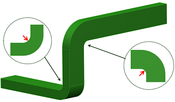
Bend RadiusCenter Bend RadiusThe center bend radius is for circular shape. The center bend radius must be higher than the half diameter of the route. Center bend radius = 0 is supported and results in a sharp bend. Inner Bend RadiusThe inner bend radius is a bend radius value for non-circular sections. The inner bend radius is an algorithm that allows to calculate a dynamic bend radius on each bend. This dynamic bend radius is equal to the value of the inner bend radius plus the height or width of the segment, following the bend orientation (up, down, left, or right). The following example shows two bend radius, one
calculated with the height and the other with the width.
Editable AttributesWith an Engineering Specification Data Setup, a route reference is an object and is stored in catalogs. So during the route reference creation or modification, the editable attributes are copied from the object reference of the catalog to the current route reference, including the customer attributes. The following commands are impacted:
Level of DetailYou can use the level of detail (LOD) mechanism in the HVAC Designapps to improve the performance of the 3D view handling. For more information, see Visual Quality Management. When using the LOD mechanism, replace 3D ducts by a dashed line representing their centerline. If you are using old data, you need to upgrade them. For more information, see Upgrading or Cleaning Route Geometry. | |||||||||||||||||||||||||||
 appears for you
to maintain the port direction and ensure a straight portion between the port and
the directional point.
appears for you
to maintain the port direction and ensure a straight portion between the port and
the directional point.  appears.