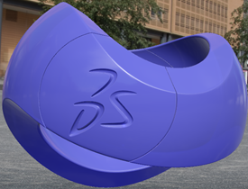
The accuracy option controls the tessellation of surfaces when in Edit mode."Tessellation" means that the surfaces of your geometry are
built using triangles. A triangulation is computed to describe the neighborhood
relation of all points.
Note:
To activate Edit mode, do one of the following:
Double-click a 3D part or a 3D shape from the tree.
From the Tools section of the action bar, click Switch to Edit Mode. For
more information, see Product Structure Design User's Guide.
You can specify a value for Proportional and
Fixed. The preview area to the right shows the
effect.
Proportional
Tessellation is calculated according to object size. The larger the object, the coarser the
tessellation. For the same sag value,
the tessellation on small objects is always finer than on large
objects.
The sag value used to calculate the tessellation of
each object is calculated is as follows:
sag = coeff. x radius of sphere/100
where:
"coeff." is the value you set using the slider (between 0.1 and
1)
"radius of sphere" is the radius of a sphere encompassing the
object entirely (this value is obviously higher on larger
objects).
Tip:
Start by setting a high fixed value to
decrease the number of tessellation triangles and thus, pay a lower
price in performance.
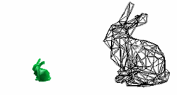
Fixed sag: same number of triangles whatever the object's size.
Proportional sag: the number of triangles is proportional to the
object's size. That is, a big object is generally tessellated
using fewer triangles.
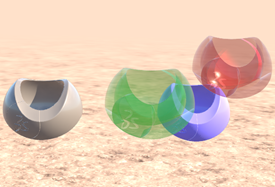
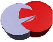
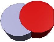
More precisely, let's take an example with the
following bounding sphere with a radius 100:
Sphere with radius 100 encompassed by its bounding
sphere (in red):
Radius of the bounding sphere > radius of sphere.
The formula used to compute the proportional sag
refers to the radius of the bounding sphere (which is > 100), hence a
coarser sag.
Mathematically speaking:
Fixed Fixed_sag = 0.2 (expression 1)
Proportional Prop_sag = coeff x radius_of_bounding_sphere /
100
If coeff = 0.2 then Prop_sag = 0.2 x
radius_of_bounding_sphere / 100 (expression 2)
As the bounding sphere of a sphere encompasses that sphere
(see pictures above), then radius_of_bounding_sphere >
radius_of_sphere
If radius_of_sphere = 100 then radius_of_bounding_sphere >
100
By dividing left and right members by 100 then
radius_of_bounding_sphere / 100 > 1
By multiplying left and right members by 0.2 then 0.2 x
radius_of_bounding_sphere / 100 > 0.2 (expression 3)
By using expressions 2 and 1 to respectively replace left and
right members in expression 3, then Prop_sag = 0.2 x
radius_of_bounding_sphere / 100 > 0.2 = Fixed_sag and
Prop_sag > Fixed_sag
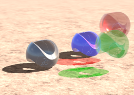
Radius = 100 mm
Prop. sag value =
0.20
Radius = 10 mm
Prop. sag value =
0.20
Radius = 100 mm
Fixed sag value =
0.20
Radius = 10 mm
Fixed sag value =
0.20
Important:
As long as the representation is not modified (for example, by creating a point, or
modifying the pad definition) the 3D accuracy is not taken into
account when you save the representation using Share > Save > Save with Options.
Bear in mind that modifying the value of the 3D accuracy has an
impact on the size of your representation because a CGR is
systematically stored in the representation, and the size of
this CGR depends on the value you set for the 3D accuracy.
By default, this option is cleared.
Fixed
Sets a fixed sag value (from 0.01 to 10) for calculating tessellation on all objects. The sag value defines the chordal deviation for
curves and surfaces.
The "curve chordal deviation" represents the maximum distance between a
polyline ("chord"), whose end points lie on a curve, and a point on this
curve.
The "surface chordal deviation" represents the maximum distance between
the tessellation triangles and the surface.
Important:
The value you enter is in millimeters (mm) and in
normal scale. If you change the range, a
multiplying factor is applied. If you change the units, the value remains in millimeters.
This value does
not vary with the object's size.
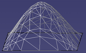
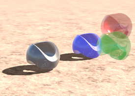
A low value means that a very fine mesh is used to render surfaces because the distance
between the geometry and the triangles in the tessellation is
very low. However, the drawback is that geometry is redrawn more
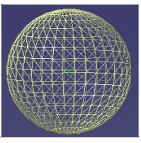
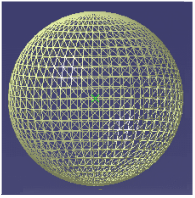
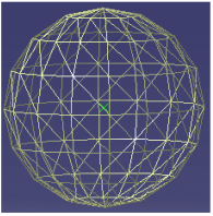
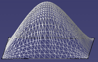
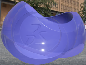
slowly when using the viewing tools. Example with default fixed sag value (=0.20)
A high value increases the distance between the geometry and the triangles and thus,
decreases the number of triangles computed on the object. This
means that a very coarse mesh is used, but the advantage is that
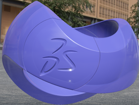
geometry is redrawn more quickly. Example with sag value value set to 8.5
By default, this option is selected.
Auto-Adaptive
Computes tessellation according to the object's curvature to best fit the context. This option is especially relevant for users working
with the 3DEXPERIENCE User Profile. It
keeps the same visual quality but the mesh weight is lighter.
Important:
The tessellation depends on the
object's size and on the selected range. For example, when Normal range is activated, the sag value is comprised
between 0.05 mm and 0.2 mm.
To check the
result, you can compare the triangle number by running
c:triangles count from the power input box.
For more information, see 3DEXPERIENCE
Native Apps: Native Apps Advanced: Viewing: Testing and Optimizing:
Triangle Counting.
By default, this option is cleared.
Curves' accuracy ratio
Lets you control the ratio of the 3D accuracy you define using the above-detailed
3D Accuracy options.
Use the slider displayed to the right to choose a value between 0.1 and
1.0.
Important:
If Auto-Adaptive is
activated, the ratio is 1.0 and cannot be modified.
The curve accuracy is calculated as follows: sag = 3D accuracy x
ratio which means that the tessellation on curves is finer
than the tessellation on surfaces.
For example, setting the 3D sag value to 0.20 and the curve accuracy
ratio to 0.10 means that:
Faces are tessellated with a 0.20 sag.
Curves are tessellated with a 0.02 sag (0.20 x 0.10).
Fixed 3D accuracy = 10 Curve accuracy ratio = 1 Fixed 3D accuracy = 10 Curve accuracy ratio = 0.10
By default, the value is set to 0.1 to have a finer
tessellation on curves in 3D.
Optimize meshes for texturing
Changes the mesh triangulation to enhance visualization when applying textures to objects.
When this option is selected, a higher number of
triangles is drawn, even on flat geometry such as a straight line, or a
planar surface.
Note:
The chordal deviation
(that is to say, the sag value) is not impacted.
This option is compatible with incremental tessellation
during the authoring process (in that case, only the new or
modified geometry is tessellated).
This option is stored in CGR format on disk. If the model is
open afterwards in authoring mode with different
preferences, then it has to be re-tessellated.
2D Accuracy
Options for 2D accuracy are the same as for 3D accuracy, except the Auto-Adaptive mode that is
not available.
Visual Quality Management
Lets you override quality parameters defined in the Visual Quality
editor for the static and dynamic rendering modes. "Static"
means that there is no interaction with objects. "Dynamic" means that the
viewpoint is modified through manipulators, a rotation, a zoom or an animation,
for example.
Click
Change Visual Quality to define your own preset
parameters through the preset editor.
By default, parameters are set according to your GPU to provide the best
quality without compromising performance. This default mode is identified by the
icon. To switch to manual override mode and change the default values, click
next to the parameter to be modified and then, depending on the parameter:
Select a value in the list.
Select or clear the associated check box, and then specify the appropriate value for the
static and dynamic modes if you are using the
Rasterizer engine. If you are using the
Ray Tracing engine, only Static
mode is available.
Important:
When manual override mode is active ( ), the values defined in this tab supersede those
defined in the Visual Quality panel (available
through the Visual Quality... command in the View section
of the action bar). This means that the same values are
applied to all widgets, whatever the profile defined in the
Visual Quality panel. In addition to this, the
values displayed in the Visual Quality panel cannot
be modified.
Therefore, prefer the use of the Visual
Quality panel to tune static and dynamic visualization
quality.
When manual override mode is deactivated ( ), the values defined in this tab are kept across
sessions but those defined in the Visual Quality
panel prevail.
Some parameters are deactivated in Dynamic mode because it is not
possible to manage different values for Static and
Dynamic modes.
Rasterizer - Ray Tracing
Select the rendering mode for which you want to tune visualization
quality.
Rasterizer lets you tune
visualization quality for the Stellar Realtime Native engine.
Ray Tracing lets you tune
visualization quality in Static mode for the
Stellar Physically Correct engine.
Manage User Presets
Lets you create, edit, or delete groups which store user-defined values for the visual
quality parameters.
To create a preset:
Click Add. You can then either leave the
default name, or click Rename..., and
then enter a name in the box.
You can create up to 10
presets.
Click Edit..., and then define the
appropriate visualization quality options. You need to restart
your session to take your changes into account.
Optional:
To delete a preset from the list, select
iit from the list, and then click Delete.
When a preset is selected in the list, its
user-defined values are automatically applied to the corresponding
visual quality parameters.
Note:
When using presets:
Restart your application to take the user preset changes into account.
After restart, the user preset is displayed in the Static
and Dynamic lists of the Visual
Quality panel, so that its values can be
applied to the current object.
Visual Quality Management - Rasterizer
Anti-aliasing
Lets you specify the number of internal renderings made to create the anti-aliasing effect.
Anti-aliasing smoothes rough edges to give the appearance of higher
resolution by taking into account how much an ideal edge overlaps adjacent
pixels.
It also avoids rendering artifacts, such as the staircase
effect, by improving the visual quality of lines and surface edges (whether
they are common or free border edges) in the whole scene. The image is
rendered internally with a resolution higher than the one on screen.
Geometry is drawn only once and for CPU-limited objects, it has a very
positive impact on performance. On the contrary, for GPU-limited objects,
the performance gain is minimal.
With this technique, each given
pixel on screen is divided into "n" subpixels: the more subpixels, the
better the result.
Option
Description
Setting
Click a value from the list to specify the quality level.
None: no super sampling.
nx where
n is the factor value: each pixel is
divided into n subpixels. The quality
is n times better.
MS is for MSAA
(Multisample antialiasing). This method draws the
scene multiple times and slightly jitters the
position of the camera for each version. The
resulting image is a blending of all the
previously drawn versions.
SS is for SSAA
(Supersample antialiasing). This method renders
the image at a higher resolution, then downsamples
it. Sharp edges are smoother with no staircase
effect.
Note:
There is a price to pay in
performance when using this method.
The higher the value, the better the quality but
there is a price to pay in performance if you choose
a very high-quality level. 8x
is a good value to start with because you can obtain
a nice result with a minor impact on performance. In
addition, do not use
Edges/Lines.
Recommendation:
Do not use your driver's
antialiasing.
Post process
Lets you select the post-process technique you want
to apply.
None: no post-process is
applied.
FXAA: applies the FXAA
(Fast approximate antialiasing) technique. This
post-process shader-based method smoothes out hard
edges (even those inside polygons) in all pixels
on the screen.
TAA: applies the TAA
(Temporal antialiasing) technique. This technique
uses the data from the previous frames and the
current frame to converge to an aliasing-free
image. It is basically a smart average between the
N previous frames. As a
consequence, it provides a better temporal
stability for pictures compared to other
techniques like MSAA (Multisample antialiasing).
You have less flickering while moving or in the
HTC Vive™.
Important:
A ghosting effect may appear when TAA is
activated.
The TAA result depends on the camera
orientation. For example, a nearly horizontal line
does not give good results.
FXAA
Lets you define the quality level when the FXAA
method is applied.
This option is relevant only when
FXAA is selected for the
Anti-aliasing Post-process
option.
Use with SSAO
Activates anti-aliasing on SSAO (Screen Space Ambient
Occlusion).
All the post-treatment effects are
anti-aliased as well: the normal and the Z map are
anti-aliased, which means that some post effects are
anti-aliased too. Therefore, activating this option
may have a negative impact on performance unless you
have at least a Fermi-based card: Quadro Q2000,
Q4000, and so on.
Important:
This option is relevant only for ambiences
using the SSAO lighting technique (such as
Clean Space). See 3DEXPERIENCE
Native Apps
User's Guide: Native Apps Advanced:
Additional Viewing Commands: Applying Predefined
Ambiences for more information about these
ambiences.
You can use this option only with graphic
cards supporting FBO, FBO with multisampling,
texture with multisampling extension, and OpenGL
3.x. Otherwise, anti-aliasing is not available.
Allow outline view mode
Allows the rendering of outline edges when the viewpoint is animated through available commands, a direct manipulation, or whenever an animation is playing.
Culling & Model
Option
Description
Min obj size (px)
This option is similar to
Level of Details and lets you
define the size of objects you want to hide or display in
your geometry.
Even if you do not want to move geometry,
it is often useful to remove details you do not need to
see. To do so, specify a high value to remove these
details. Setting a high value also enables you to move
large parts more quickly.
On the contrary,
setting a low value displays the details. For example,
setting 2 means that objects
whose size on screen is lower than 2 pixels are static.
Level of details
Defines the display
precision for your objects.
A LOD (Level of Details) is an
approximation of the mesh intended to reduce the number
of polygonal objects in modeling. The purpose of the LOD
mechanism is to adjust the polygonal representation of
an object to the distance of the user.
Specify a
low value to see all the details, or a high value to
remove details.
This option is relevant when:
You do not need a high level of detail in your
geometry. For example, because some portions are
obscured by a visible piece of the object, or are
far enough away to make the detail
meaningless.
Representations support LOD. Otherwise, it has
no effect.
The object is near the observer. It occupies a
large number of pixels on the screen and a precise
LOD is required to have a nice rendering. The object is far from the observer. Only a few
pixels are used and a rough LOD is enough to render
the object.
Occlusion
Lets you improve rendering
performance by rendering only visible objects.
Objects
occluded (hidden) by another object are detected and
prevented from being rendered, which optimizes memory
consumption and CPU usage.
Strategy
Lets you choose the size of
the bounding box for occlusion culling.
Precise corresponds to
the standard bounding box (1.0)
Optimal corresponds to a
slightly bigger bounding box (1.25)
Fast corresponds to a
bigger bounding box (1.6). This option gives a
faster result but there is a price to pay in
performance.
Important:
Activate Occlusion
first, otherwise the Occlusion
Strategy list is grayed.
Static and
Dynamic modes must use the
same occlusion strategy.
By default, this option is set to
Precise.
Force
rendering
Activates rendering
optimization on scenarios where visual elements are created
(for example, skeleton bones on DELMIA manikins, or VR scenarios with interactors).
Option is cleared
Option is selected
Important:
This option is available in
Static mode only.
As internal data is reorganized, there might be
an impact on performance depending on the number
of loaded and displayed data.
By default, the option is cleared for all profiles except
Immersive in the
Virtual Reality list.
Transparency
Tip:
For partially transparent objects, the higher the value, the better the result. But
for textures with opaque elements, a Fast quality
mode might produce a better result than a Balanced
one.
To help you with your choice, some transparency modes are associated
with the presets available in the Static and
Dynamic lists. For example, choosing the
Ultra preset automatically applies the
Order Independent Colored transparency
mode.
Transparency Mode
Description
Alpha Blending Without Sort
Produces an effect similar to looking through clear glass.
Use this option when you need to
view several transparent objects located at different
depths of a scene. For example, looking through a car
windscreen at other opaque objects inside the car.
This effect is impacted according to the value you
specify. You need to specify the transparency
coefficient on selected objects through the
Transparency slider in the
Properties dialog box. See 3DEXPERIENCE
Native Apps
User's Guide: Native Apps Advanced: Editing
Objects: Editing Graphic Properties for more
information.
Regarding polygons, the result might
not be as expected because the triangles are blended
with the rest of the scene. As it is too costly and may
adversely affect performance, transparent polygons are
drawn at the end of the draw phase but are not
depth-stored. Therefore, when the transparent polygon is
blended, the scene might not be fully drawn behind.
Important:
When working in Shading with
Material mode, if you apply the
maximum value (that is, 255) to the transparency
in the object properties, then nothing is
displayed in the work area.
This mode is computation-intensive and
consequently has an adverse effect on display
performance.
Alpha Blending
Similar to Alpha Blending Without Sort, except that objects are sorted
according to their distance from the viewer. This gives
slightly better results.
Weighted Average
Improves the quality of transparent rendering, and renders mixed opaque/transparent geometry.
This rendering technique also improves the visualization
quality of edges: edges in the back are less visible than
edges in the front, and their colors are blended with the
geometry.
This technique applies to 3D geometry only and has no
impact on other transparent geometries such as the Compass.
Warning:
Shaders must be supported.
GL_EXT_blend_func_separate must
be supported.
Floating textures must be available on the
device.
When this option is selected, there is a price to
pay in performance because more memory/CPU is used. In
full screen mode, approximately 30-40 Mo of textures are
allocated. As the scene is drawn many times, the higher
the number of transparent faces, the higher the impact
on performance.
Note:
About this mode:
Mirroring with alpha blending is rendered in
classical mode and therefore, visual artifacts
might occur especially for objects with edges.
When the geometry contains a high number of
layers, the back edges seem to disappear. The
reason is that an average on the layer is
computed, and the edge color has no significant
impact on the computation.
This mode does not support MSAA (Multisample
Anti-aliasing).
Order Independent
This technique lets you render transparency in your scene by sorting geometry per pixel. It
provides the highest transparency quality.
Important:
Refraction and roughness are not
taken into account.
Order Independent Colored
Provides a better real time transparency by taking into account the albedo color, absorption
color, attenuation distance, and Fresnel color.
Important:
Refraction and roughness are not
taken into account.
Shadows
Shadow Type
Description
On ground
Simulates the shadows of
the objects on the ground, provided that the current
ambience supports this effect.
Inter objects
Enables shadow-casting
between objects.
From transparents
Enables transparent objects
to cast shadows on opaque objects and on the ground but they
do not receive any shadows from other objects.
From area lights
Renders soft shadows cast
by rectangle, disk, or sphere area lights. You can have up
to 4 area lights.
This option can be used with the Inter
objects option.
Important:
This shadow type requires a GPU supporting
Vulkan ray tracing.
The On ground option has
no effect on shadows cast by area lights.
This option is not available for the
Virtual Reality mode.
The following capabilities are not supported:
Multi-GPU environment
Large scale models
High-memory pressure
Local clipping planes
Shadows cast by transparent objects.
Max map size
Defines the maximum
resolution at which shadows are rendered.
The higher the
resolution, the sharper the shadows.
Use bounding box
Uses the bounding box
around the selected object (the bounding sphere) instead of
the scene bounding box when casting shadows.
The scene bounding box casts more precise
directional shadows. However, as the box is
recomputed based on all triangles in the object
whenever the scene is modified, there is a price
to pay in performance.
The bounding sphere takes less time to recompute
but casts less precise shadows.
Filtering to use
Lets you select the method
to use when filtering the shadow map.
PCF (Percentage-Closer
Filtering) calculates the percentage of the surface
that is closer to the light.
ESM (Exponential Shadow
Mapping) enables hard shadow anti-aliasing.
PCSS (Percentage-Closer Soft
Shadows) uses a variable penumbra to render
realistic soft shadows.
Filtering quality
Lets you define the quality
level to apply when filtering the shadow map.
Reflections
Option
Description
On ground
Lets you apply a mirror or
SSR effect.
None: no mirror effect is
applied.
Mirror: applies a mirror
effect on the ground, and hidden objects are also
reflected.
SSR: SSR (Screen Space
Reflections) replaces the mirror effect on the
ground, but only visible parts are reflected. This
avoids rendering hidden parts when computing
reflections and may be useful when working with
heavy objects.
SSR allows simple reflections
on reflective objects from other objects visible on
screen. SSR can replace the mirror effect in predefined
ambiences.
Inter objects
Lets you display
inter-object reflections.
None: no reflections are
displayed between objects.
SSR: displays inter-object
reflections using the SSR algorithm.
None
SSR
You can use SSR for inter-objects
reflections in the following ambiences:
White Review
Dark Review
Outdoor
Indoor
City
Road
All ambiences where the mirror effect can be
replaced.
SSR quality
Defines the level quality
for the Screen Space Reflections (SSR) algorithm, either
Low or
High.
Use the
Screen space reflections
quality option with the
Reflections on ground, or the
Reflections between objects
option.
Ambient Occlusion
Option
Description
Allow
Displays shaded surfaces by considering light attenuation from nearby actors. The theory is
when an object is surrounded by many other objects, it
appears darker because less light can reach it.
Mode
Lets you select the type of ambient occlusion.
SSAO: SSAO (Screen Space
Ambient Occlusion) is a simplified calculation of
the global indirect illumination. It produces
enhanced realism by taking into account light
attenuation caused by occluding objects. With this
technique, the scene is equally lit with soft
shadows and small surface details are accentuated to
give more relief.
HBAO: HBAO (Horizon-Based
Ambient Occlusion) provides a more accurate ambient
occlusion.
When this
option is activated, you can use the
HQAO cache size option to
define memory usage for the cache. Keep in mind
that using less memory uses more compute power
every frame to compute things that are not stored
in the cache.
Important:
For both
SSAO and
HBAO:
There is s small radius of impact. It is not
made to have large smooth shadow on the floor.
There is a price to pay in performance.
As these techniques are an approximation of
ambient occlusion, it might not work in all cases.
Some artifacts might appear on screen for
edges because there is no data.
For HQAO:
This option is available only if your graphics
card supports the required features
(vk_nv_ray_tracing extension).
Activating HQAO deactivates Max
sampling, Blur
mode, and Max blur
level.
The following capabilities are not supported:
multi-GPU environment, large-scale models,
high-memory pressure, and local clipping
planes.
Max sampling
Lets you define the maximum number of depth samples per pixel for ambient occlusion.
Blur Mode
Lets you select the blur type.
None: no blur effect.
EDZ: fast blur with edge
detection from Z-depth.
EDZN: fast blur with edge
detection from Z-depth and normal.
AEDZN: high-quality blur with
accurate edge detection from Z-depth and normal.
Max blur level
Lets you define the maximum shadow sharpness for ambient occlusion.
HQAO cache size
Lets you define memory usage for the cache.
For example, using less memory uses more
compute power every frame to compute things that are not
stored in the cache.
Bloom
Allow Bloom
Applies a glow-like effect on brightly lit objects.
Max quality
Lets you define the maximum quality level applied to the bloom effect.
Allow depth of field
Makes portions of the scene away from the camera focal
point appear blurred.
Enable multi-color capping
Lets you use multiple colors for the capping plane when
running sectioning commands or clipping tools.
To edit the
capping plane, right-click in the 3D area.
Note:
This option is relevant only for geometry
created with the 3DEXPERIENCE.
Downsampling factor
Lets you enhance the rendering performance by applying a downsampling factor to the image
displayed on-screen.
The image is generated with a lower resolution to have
better performance but with a lower visual quality (the image looks slightly
blurry).
This option is especially relevant on laptops with a low-end
graphics card. In this case, selecting Medium or
High provides a good quality/performance ratio.
By default, this option is set to
Ultra.
Material
Option
Description
Metallic flakes quality
Lets you tune the simulation quality of
flakes (thin and highly reflective particles) at interactive frame rates when a
car paint material is applied.
The frame rate defines the number of images
displayed per second (FPS). The higher the FPS, the better the result. Virtual
Reality scenarios, for example, require a very high FPS.
Low: no individual flake is visible, only a rough
approximation.
This value is used by default for the
Immersive preset.
Medium: some flakes are visible, but not all of
them.
High: most of the flakes are visible.
Ultra: all the simulated flakes are visible (with
two different colors).
Closeup flakes mode
Lets you activate or deactivate large flakes
on car paint materials.
Depth Buffer Options
Option
Description
Buffering mode
Default means that normal
depth buffering is activated.
Log means that the
logarithmic Z buffer is activated. This provides
better depth precision, which is useful for
large-scale models, but there is a price to pay in
performance.
Offsetting mode
Edge means that the edge
rendering technique is activated. When edges are
drawn, some artifacts (such as specular aliasing)
that might occur on surfaces are corrected. There is
a price to pay in performance.
Face is the default mode and
provides optimal performance.
Flickering
reduction
Improves visual quality by
reducing visual artifacts (called "Z-fighting" or stitching
effect) that may occur with overlapping models.
The scene
is prerendered in the depth buffer, without rendering
any colors. The depth buffer is a simple 2D image
containing depth values of an individual pixel on
screen. It is used for comparing the current pixel's
depth value with the value already present in the
buffer, before deciding to overwrite it.
Once the
depth values have been retrieved, the scene is rendered
again and:
A bias is added to the computed z-values.
Comparisons are made, but nothing is written to
the depth buffer. Color values that fail the
comparison are overlapped.
Visual flickering is thus significantly
reduced by overlapping zones. However, there is a price
to pay in performance because the frame rate is
decreased. The bigger the model, the more significant
the decrease.
Option is cleared
Option is selected
Important:
This option may have no effect on small
structures, and overlapping surfaces with high
curvature.
This option does not work in ray tracing view
mode.
By default, this option is cleared.
Visual Quality Management - Ray Tracing
Important:
You can only configure parameters for the
Static mode.
Accumulative Settings
Option
Description
Target quality (dB)
Defines the quality of the converged image as peak signal to noise ratio
(PSNR).
Low values (between 10 and 20) result in noisy images and a quickly
finishing convergence and are suitable for preview rendering.
High
values (between 40 and 70) result in images without apparent noise but with a
convergence time that might be very long. Such values are suitable for final
frame rendering.
Samples per frame
Defines how many samples per pixel are traced before displaying the first
ray tracing image.
1 enables maximum interactivity. Set to values above 1
makes the first image less noisy at the cost of lower interactivity.
Recommendation:
Use values above 1 only for compute setups with high
compute power like multi-GPU and cluster setups.
The value of
this option varies exponentially (1, 2, 4, 8, and so on).
Max sample luminance
Lets you activate or deactivate the maximum sample luminance option.
If
you activate this option, some parts of the computed images may be darker than
they should be in reality. In return, image noise converges more
quickly.
Base value
Defines the clamping value of result pixels.
Lower values result in
faster convergence but darken bright effects like highlights or emissive
objects.
This value is used as maximum sample luminance value for sample
paths consisting of many ray bounces. For paths including just few ray
bounces, or only specular bounces, higher max sample luminance values are
used.
Filtering
Lets you activate or deactivate the Gauss anti-aliasing filter.
Strength
Defines the Gauss filter curve used for smoothing. The higher the value,
the smoother the result.
This option is available only when
Filtering is activated.
Denoiser
Converts a noisy image into a smooth image and improves convergence time
for a rendering.
Click Denoiser, and then use
Start iteration option to specify after how many
frames the denoiser is enabled.
Recommendation:
Enable denoising
only if the amount of video memory (VRAM) is above 8 GB.
The
Denoiser option can be activated if your GPU is:
a NVIDIA GPU with a compatible NVIDIA driver installed.
generation Maxwell or newer (for example, Maxwell, Volta, Turing,
Ampere).
Note:
About the denoiser:
There is a kind of artistically painted style effect in the early
stages, but this effect is removed when the image has converged more.
Enabling the denoiser automatically grays out the
Denoiser option in the Visual Quality
Manager.
Start iteration
Applies the denoiser after the specified number of iterations.
Global Illumination
Option
Description
Max path depth
Defines the maximum number of ray bounces.
Light Tracing
Optimizes simulation of caustics effects and indirect illumination.
Recommendation:
Use this option for scenes with small light emitters or very glossy
surfaces, and for interior scenes.
Clear this option in standard scenes for faster interactivity and
convergence.
Fast subsurface scattering
Lets you switch between fast and accurate subsurface scattering simulation (SSS).
Fast SSS converges significantly faster but is only an approximation to
reality.
Recommendation:
Use it for concept design and
marketing.
Accurate SSS is physically-based but converges a lot slower.
Recommendation:
Use it for concept validation and light
visualization.
Ray offset (mm)
Specifies the offset from a ray hit point at which new rays start.
Downsampling factor
Lets you enhance the rendering performance by applying a downsampling factor to the image
displayed on screen.
The image is generated with a lower resolution to have
better performance but with a lower visual quality (the image looks slightly
blurry).
Miscellaneous
Enable isoparametrics generation
Displays the topological elements defined as being
isoparametrics.
To use this option:
Select Enable isoparametrics generation.
Restart your session.
Access the Performance tab, and then use
the Number of isoparametrics in U and V
arrows to specify the number of isoparametrics for U and V axes.
You can display up to 10 isoparametrics.
From the View section of the action bar, click Customize
View, and then select Isoparametrics.
By default, this check box is cleared for performance reasons.
Enable two side lighting for faces and surfaces only
Helps you visualize the two sides (that is, front side and back side) of a face or surface by
lighting them.
By default, this option is selected.
Enable back face culling
For stand-alone faces
Avoids redisplay of back sides of faces or surfaces.
When this option is selected along with Enable two side
lighting for faces and surfaces only, only front faces
are lightened.
Important:
The back side of faces is determined by the OpenGL
specifications (using the first triangle orientation and the normal of
the face) and not by the line-of-sight vector of the viewpoint. If a
face disappears when this option is selected, it means that this face is
a back side face.
By default, this check box is cleared.
For faces belonging to solids
Avoids redisplay of back sides of faces or surfaces belonging to
solids.
By default, this check box is selected.
Important:
Activating the For faces belonging to
solids option has an impact on the
Depth Effect command.
Faces of a solid or of a surface are visualized according to the
orientation of the solid's or surface's normal. This enables to
know whether a face is considered as a back face or not and
therefore, whether it can be impacted by these options or not.
Clearing these options has an impact on performance because back
faces that were not previously drawn are systematically
rendered, whether they can be seen by the user or not.
Halo when displaying the geometry with hidden lines
removed
Enabled
Displays a halo around intersecting edges to create a
perspective effect.
Prior to using it, switch to Dynamic hidden line
removal mode. Otherwise, you cannot use this option. To
do so, from the View section of the action bar, click Customize
View in the Shading flyout then select the
Dynamic hidden line removal check box before
clicking OK to validate.
By default, this check box is cleared.
Picking
Enables you to pick elements, that is, select elements when pointing them.
In "normal" picking mode, you need to move your mouse to select
an element whereas in accurate picking mode, the slightest move (one pixel, for
example) is enough to select.
Window size for picking
Lets you specify the size (in pixels) of the panel to be used for picking elements in normal
mode. You can set a value comprised between 1 and
100, the default value being 4 pixels. The smaller the value, the more
precise the picking.
Enable accurate picking
Helps you select more precisely elements that are very close to each other when displaying
the geometry. It is recommended to work with a
magnified view of your document by selecting View > Magnifier.
For more information, see 3DEXPERIENCE
Native Apps: Native Apps Common Services:
Additional Viewing Commands: Manipulating the Viewpoint.
When the Enable accurate picking check box is
selected, the Window size for accurate picking
box is selected to let you define the size of the panel (in pixels) used
for accurate picking. The maximum value you can enter corresponds to the
maximum value defined for the "normal" picking, that is, the value
defined using the Window size for picking box.
This option enables you to use normal picking as well.
Important:
Activating this option might have a negative
impact on performance for big objects.
By default, this check box is cleared.
Video Memory Management
Memory Unloading
Unloads memory when 90% of the GPU is occupied. The existing in-use memory is packed into a
compact space.
If selected, the Enable
video memory unloading option allocates memory for GPU
buffers using a new buffer allocator and optimizes memory for objects
transferred to the No Show space, out-of-view objects, and objects
located in non-visible tabs.
Important:
This option is relevant for the rasterizer (Stellar
Realtime Native engine) only.
By default, this check box is cleared.
Mesh Compression
Reduces memory consumption on the GPU (around 30%) when importing models.
To do so, the angular precision of the normal (and
if available, the tangent and binormal) of each vertex is reduced. You
can thus visualize larger models on a wider range of computers.
If the Enable Model Normal
Compression option is selected, visualization is
compressed by downgrading the model accuracy.
Important:
Only mesh geometries are eligible for compression.
This option impacts the model visualization only, not its data.
It might take more time to load models.
Artifacts might occur on specular reflection involving mesh
with high curvature.
 . For
more information, see Product Structure Design User's Guide.
. For
more information, see Product Structure Design User's Guide.

 > Save > Save with Options.
  By default, this option is cleared.
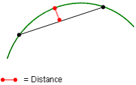
 icon. To switch to manual override mode and change the default values, click
 ), the values defined in this tab supersede those
defined in the
), the values defined in this tab supersede those
defined in the  command in the


 , and then select Isoparametrics.