-
From the Edition section of the action bar, click Break Curve
 . .
-
In the Elements box, select the curve to be trimmed.
The element to be trimmed appears in green. 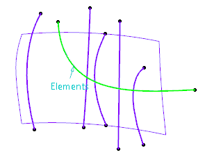 -
In the Limitation box, select or create the trimming
element(s).
You can click at any point on the curve, use the contextual
commands available on the Limitation box, or click  . .
- Select the surface and the curve.
The trimming elements appear in red. 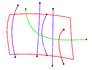 Note:
Right-click on a
Limitation tag to access the context menu for Extrapolation and Projection which
are also available in the dialog box.
-
Click Apply.
The selected curve is trimmed into two parts. The plain
part of curve is kept and the dotted part is removed.
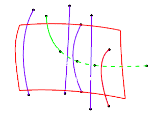
-
Click the curve segment to be kept to switch between kept and removed part.
The selected segment is displayed with a plain line. 
-
Right-click any re-limited element to display the context menu.
- Keep all: Keeps all parts of the all curves.
- Keep all but this: Keeps all parts of all curves except the
selected one.
- Remove all but this: Removes all parts of all curves except
the selected one.
-
In the Projection area, click Along Robot
 , then click Apply. , then click Apply.
The elements that do not lie on the trimmed elements will be projected
(pseudo-intersections) onto the trimming elements according to the Robot direction. 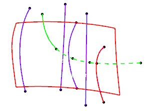 - Optional:
In the Extrapolation area, select an extrapolation type.
If the element and the limitation curves do not intersect each other, they can be
extrapolated. The intersection points are used to trim the input curves.
Each selected curve is provided with a point handle at its center to choose
vertices of the curves. 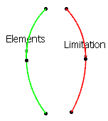 Each handle has four
states:
- Closest: This is the default mode. The closest vertices are
extrapolated.
- Start: A single-directional arrow handle pointing to the
curve's start vertex appears in addition to the point handle. The start vertex is
extrapolated.
- End: A single-directional arrow handle pointing to the
curve's end vertex appears in addition to the point handle. The end vertex is
extrapolated.
- Both: A bi-directional arrow handle pointing to both curve's
start and end vertices appears in addition to the point handle. Both vertices are
extrapolated.
Note:
In case of multi-domain curve bodies, no handles are provided on the curves.
The closest domain of the body is used for the extrapolation.
- Optional:
Click on a point handle to access the Start handle.
- Optional:
Click the start handle to revert its direction to End and vice
versa.
- Optional:
Right-click a point handle and select Closest or
Both.
-
Click on the element's point handle.
An arrow handle appears pointing in the direction of the curve's start
vertex. 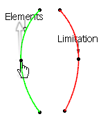 -
Click Apply.
The curve is extrapolated at its start vertex. 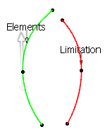 -
Click OK.
Notes:
- You can select a surface edge as the element to be trimmed. In this case, a new
datum curve is created and added to the selection.
- If you select a surface edge as the trimming element, the Break
Both
 option converts this edge into a datum curve. option converts this edge into a datum curve.
- The Keep Original setting in the Tools
Dashboard area of the App Options panel is locally saved for the Break command when you exit
the command by clicking OK.
|
 option converts this edge into a datum curve.


