Breaking Surfaces | ||||||||
|
| |||||||
-
From the Edition section of the action bar, click Break Surface
 .
.
-
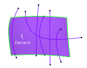
In the Elements box, select the surface.
The edges of the surface appear in green.
-
In the Limitation box, select the trimming curves.
You can directly select an intersection curve resulting from a Cutting Plane Analysis as limiting element.
The limiting elements appear in red.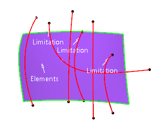
- Optional:
Click on the surface to create an instant iso-parametric curve as the limiting element.
This curve can be positioned using the handle which appears on the curve.
- Right-click on a point handle and select Propagate to propagate the isoparametric curve onto adjacent surfaces.
- Clear Propagate Isoparametric Curve before creating an instant iso-parametric curve to avoid the propagation of an iso-parametric curve onto adjacent surfaces.

- Optional: Right-click a Limitation tag to access the context menu.
-
Click Apply.
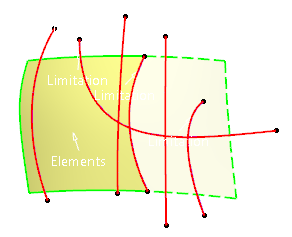
The surface is trimmed.
By default, only one trimmed element is kept (the part of the surface bounded by the solid lines).
-
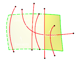
Click the segment to be kept to switch between kept and removed part.
The edges of the segment appear as solid lines.
-
Right-click any re-limited element to display the context menu.
- Keep all: Keeps all parts of the all surfaces.
- Keep all but this: Keeps all parts of all surfaces except the selected one.
- Remove all but this: Removes all parts of all surfaces except the selected one.
Tip: Hold down Ctrl and select the elements to keep or remove them. - In the Projection area, click Along Robot
 .
. -
Click Apply.Elements that do not lie on the trimmed elements will be projected (pseudo-intersections) onto the trimming elements according to the Robot direction.
-
In the Projection area, click Along
Normal
 , then click Apply.
Elements that do not lie on the trimmed elements will be projected (pseudo-intersections) onto the trimming elements according to the normal direction.
 -
In the Trim Type area, click Surface Trim
 , then
click Apply.
- The maximum deviation is displayed and on the geometry (yellow label).
- The maximum degree variation allowed for each patch of the new surface as compared to patches of the initial surface can be modified.
- In the Order area, select Keep Order to edit the U and V values.
- Optional:
In the Extrapolation area, click Tangential
Extrapolation
 .
.
-
Click Apply.
The surface segments are added along the tangent direction.
- Optional:
Click IsoUV Extrapolation
 .
.
-
Click Apply.
The input elements are trimmed by extrapolating the limiting elements. By default, the shortest iso side in U direction is used to trim the surface.
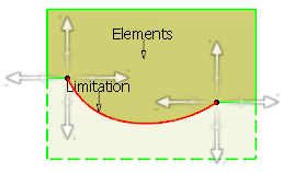
4-directional arrow handles appear at the end points of the limiting elements to select any of the iso-extrapolated sides to trim the surface in both IsoU and/or IsoV direction.
-
Click one or more arrows to select the required iso side(s).
The trim result appears in the direction of the arrow handles.
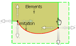 Notes:
- Undo/Redo is provided for arrow handle selection.
- Arrow handles appear only if an extrapolation is required.
- Click OK.
Note:
The Keep Original setting in the Tools
Dashboard area of the App Options panel is locally saved for the Break command when you exit the
command by clicking OK.