Flange - Advanced Tab | |||||||||
|
| ||||||||
Options
- Type
-
- None
- Nothing is defined.
- Target
- The flange surface starts from a target surface to be selected via Reference. The resulting flange is moved to the target surface. Guide and angle are used as input parameters.
- Connect
- The resulting flange ends on the selected Reference. The reference element can be a surface or a plane.
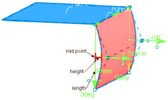
Overcrowning
(in ICEM Shape Morphing only)
The created flange surface can be overcrowned either by specifying a crowning factor or a draft angle. Both Sides is disabled when selecting Overcrowning.
- Factor
- The crown height at the mid point of the flange is the result of
the multiplication of crown factor and length of the flange (not overcrowned).
- Angle
- The draft angle is the angle by which the tangent is rotated at
the flange end.
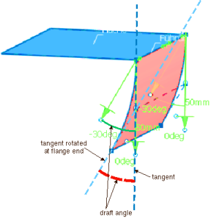
- Individual crown
- You can specify the draft angle individually for each point using the manipulators.
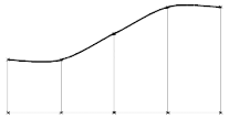
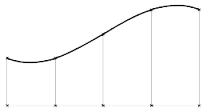
Shape
(in ICEM Shape Morphing only)
Influences the flange shape, if the flange has at least one inner manipulator and individual values are set for the parameters Length, Angle or Overcrowning.
If Shape check box is cleared, the setting Smooth Shape is used as default.
 |
 |
 |
 |
Corner
If a complex guide curve consisting of connected lines and fillet arcs is selected, the flange has no G2 continuity between the separate parts.
Calculates a flange with corner surfaces to obtain a smooth control point mesh at corners where the different parts have G2 continuity.
In the More info area, Corner must be selected.
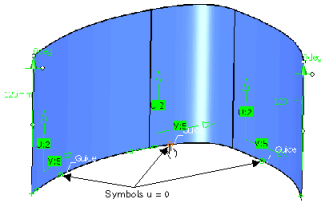
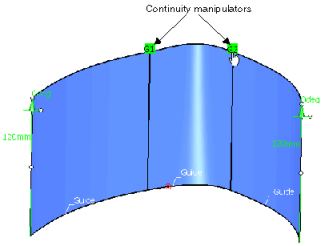
After selecting a symbol and clicking Apply, the following manipulators are created at the opposite edge of the selected symbol:
- Continuity manipulators
Clicking the continuity manipulators toggles between G1 and G2 continuity.
- Tension manipulators
Moving the tension manipulators modifies the tension factor as well as all control points except those at the guide edge.

If the corner surface is computed, manipulators for the transition values to the adjacent surfaces as well as tension manipulators are available to decide, which form factor shall be used to compute the blend curve.
- The continuity and tension manipulators are only displayed if
Continuity
 and
Tension
and
Tension
 in the
Tools Dashboard are selected.
in the
Tools Dashboard are selected.
- A corner can only consist of one cell.
- The start and end cells of a wire are not allowed to be selected as corner cells.
- Also adjacent cells to a cell selected as corner are not allowed to be selected as corners.