in normal direction of the base surface, if surface edges have
been selected as guide curve, or
in normal direction of the target surface, if the guide curve
is a curve segment or curve.
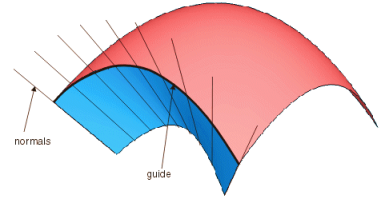
Shell normal
The basic flange direction runs in direction of the normals
in each point of the guide on the selected surface.
If the guide does not lie on the surface, it is projected
normal onto the surface, and the normals in the projected points define the
basic flange direction.
Guide + prio. tangent
The basic flange direction is generated from a moving frame
type that is aligned by the normal plane in each point of the curve and by the
direction defined in the
Orientation box. The moving frame type
runs tangentially to the guide and thus may define a different flange direction
in each curve point.
Guide + prio. direction
Defines the basic flange direction by a moving frame which is
only aligned by the direction specified in the
Orientation box without taking into
account the curve tangent or normal plane. The basic flange direction is equal
in each curve point.
Moving frame
Defines the flange direction by a moving frame (see
Moving Frametab).
Guide
Selects one or several guides. Following elements can be selected:
These options are only available for
Shell normal.
Selects one or several surfaces or planes, whose normals specify
the basic flange direction in the points of the guide.
Basic surface
If a guide is projected onto a face selected as support and
the result lies in the trimmed area of the face, the flange will not be
completely computed along the guide.
If
Basic surface is selected, the guide is
projected onto the basic surface of the faces.
If
Basic surface is cleared, the guide is
projected directly onto the selected faces.
Note:
The projection of the guide onto the
underlying surfaces of faces is only possible in case of support surfaces being
selected with
Surface for
Shell normal, but not onto faces
selected as target surfaces with
Target on the
Advancedtab.
More Info
Displays deviations and output results.
Display
Displays values in the
work area.
U+V
Displays the UV vectors of curves and surfaces.
MFT
Displays the local coordinate system for the moving frame type.
Corner
The display of the
Corner manipulators can be selected and off.
Invert
The display of the manipulators for inverting the direction of
individual wires in the selection of guide curves can be switched
on and off.
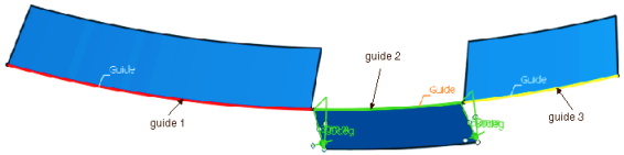
If the selection of the guide curve includes several wires, the direction of the individual wires influences the result calculation.
The invert manipulators indicate the intrinsic wire flow direction of the selected wires and allow to invert the direction of individual wires in order to obtain an optimal result.
Guide selection without
manipulators
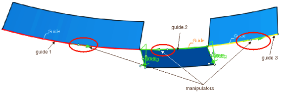
Guide selection with manipulators
and display of the intrinsic flow
The manipulator shows the intrinsic flow direction per wire
(display color: green).
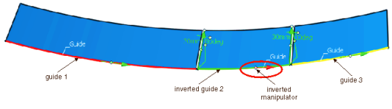
Guide selection with manipulators
and inverted flow
Clicking the middle manipulator handle inverts the direction
(display color: red).
Apply Modes
Defines the update mode of the active feature while editing it.
Dynamic
Feature update occurs dynamically when moving handles or editing parameter
values by sliders in the dialog box.
This option is not available for each command.
Static
Feature update occurs only after releasing the handle.
Preview
Displays a preview when geometry is modified by means of the handle and LMB pressed. The
original geometry remains unchanged. Feature update occurs only
after releasing the LMB.
This option is not available for each command.
None
Feature update occurs only after selecting Apply.
Deviation
Guide
Displays the deviation of the approximated guide.
Shape
Displays the deviation from the flange.
Output Result
Max. order
Indicates the maximum order of the result created in both U and V.
Max. segments per cell
Indicates the maximum number of segments created in U and V direction.
No. of cells
Indicates the number of cells created in the result.
Manipulators and Contextual Commands
The created flange surface can be modified as follows using the
manipulators:
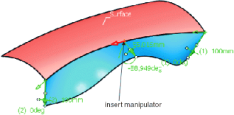
Moving the drag manipulator on the guide, you can add additional
manipulators allowing to specify individual lengths and angles:
The flange surface can be restricted to a partial region:
Pressing the control key allows simultaneous manipulations
of length and angle. In this case, however, individual values will be equated.
At the manipulator handles, right-click to activate contextual
commands with the following options:
Edit
Modifies the parameter value in the dialog box
Tuner.
Keep this point
(for angle modification only)
Creates a point at the current position of the manipulator.
Spread all
(for angle and length modification only)
Assigns the current value to all other manipulators.
Delete
(for additionally inserted manipulators only)
Deletes the manipulator.
Invert
Inverts direction or angle. Corresponds to
Invert direction/angle for
Length and
Angle.