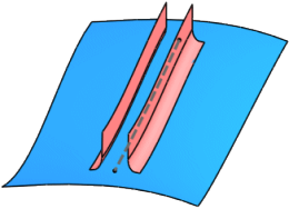
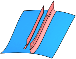
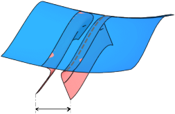
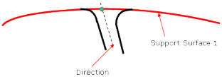
Selects the supporting surfaces on which the gap type element is to be created.
Surface 2
Selects an alternative set of support surfaces. For example, the Surface 2 support surfaces may be of a different shape and position to that of the surfaces used in Surface 1.
Surface 1
Surface 2
Gap Parameter
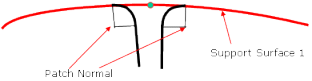
Alignment
Normal to surface 1
The draft angle of the gap feature is measured from the surface normals used in Surface 1.
Direction
The draft angle of the gap feature is calculated from a given direction selected or created by the user. The direction field becomes active when this option is chosen.
Normal to Surface
Direction
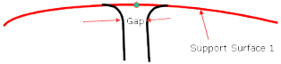
Distance
Defines the distance between the resulting gap surfaces.
The gap surfaces are calculated depending on the selected gap type.
Parameter value is stored within the tree.
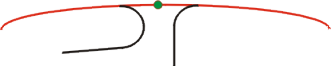
Individual Distance at each Manipulator
The gap distance can be individual at each handle.
A new handle can be created by moving the contact point in the middle of the guide.
True distance
This option is only available for the Crimp - Crimp gap type.
Off: Calculates a gap surface with a visible gap.
On: Calculates a gap surface where the center of the fillet surfaces has a distance of radius 1 + radius 2 + distance. It is measured in the adjacent moving frame plane.
Note:
If the surface normal and the y-axis of the moving frame are not parallel, the true distance of the fillets of side 1 and side 2 are smaller than the distance value.
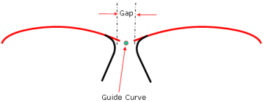
Position
Defines the gap position relative to the guide curve. Three options are available:
Center line
Side 1
Side 2
Parameter Side 1/Side 2
Variant
Only available for Crimp - Crimp and Crimp - Flange.
These options allow the user to alter the type of fillet flange result on one side according to the selected gap type.
The following combinations are possible for the Crimp - Flange:
Side 1
Side 2
Crimp
Flange
Crimp + Flange
Flange
Flange
Crimp
Flange
Crimp + Flange
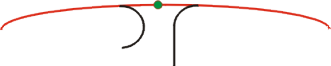
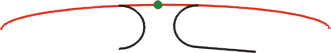
The following figures illustrate the available combinations depending on the gap type:
Gap Type: Crimp - Crimp
Gap Type: Crimp - Flange
Variant: Crimp - Crimp
Variant: Crimp - Flange
Variant: Crimp - Crimp Flange
Variant: Crimp Flange - Flange
Variant: Crimp Flange - Crimp Flange
Continuity
Only available for Crimp - Flange with variant Flange.
Defines the continuity setting for the resultant fillet:
G0
No fillet is created.
G1
Tangency continuity is maintained between the fillet and support surfaces.
G2
Curvature continuity is maintained between the fillet and the support surfaces.
Radius
Defines a radius value across the full length of the fillet.
Parameter value is stored within the tree
Chordal
A fillet with chordal parameterization is created.
True minimum radius
Defines the minimum radius.
Min. radius
Only available for Flange.
Defines a minimum radius across the full length of the fillet.
Parameter value is stored within the tree.
Offset
Only available if the support surface is not trimmed.
An offset is added between the support surface and the side of the gap. Positive values define an offset on the side of the gap, negative values on the other side.
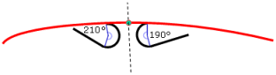
Crimp angle
Only available for Crimp and Crimp - Flange.
Defines the angle in which the flange portion of the section is angled. The angle must be
greater than 180deg. If in the case that the variant Crimp -
Flange is used, the angle is 360deg, no flange length can be
specified.
Parameter value is stored within the tree.
Length
Defines the flange length.
Offset distance
The flange ends at the specified distance from a reference support surface based on the selected
guide elements and the chosen alignment. This option allows you to compute the
distance independently of radius and angle values.
Angle
Defines the flange angle.
Draft direction
For both sides only available for Flange - Flange.
For the variants Crimp - Flange and Zero Gap, the draft direction can only be specified for one side.
Extrapolation
Extrapolates the crimp surfaces at the start and/or end curves until the edges of the support.
No Extrapolation
Extrapolation Side 1 Start and End
Measure: Force Crimp - Crimp
Only available for Flange - Flange.
Forces the measure of the gap to use the method of Crimp - Crimp
type even for Flange - Flange.
Parameter values are stored within the tree.
Approximation Tab
The approximation can be computed individually for each side if the link symbol is inactive. For
the general description of the Approximation tab, see the corresponding related topic. The
Approximationtab of the Create Gap dialog box
includes the following additional options:
Gap Distance
Tolerance
Defines the tolerance for gap calculation between each fillet.
Shape
These options can be used to specify the shape of the lofted surface, i. e. the transition type between the individual selected profiles and guides.
Linear Shape
Local Shape
Smooth Shape
Global Shape
More Info
Displays deviations and output results.
Display
Displays values in the work area.
U+V
Displays the UV vectors of curves and surfaces.
MFT
Displays the local coordinate system for the moving frame type.
Apply Modes
Defines the update mode of the active feature while editing it.
Dynamic
Feature update occurs dynamically when moving handles or editing parameter
values by sliders in the dialog box.
This option is not available for each command.
Static
Feature update occurs only after releasing the handle.
Preview
Displays a preview when geometry is modified by means of the handle and LMB pressed. The
original geometry remains unchanged. Feature update occurs only
after releasing the LMB.
This option is not available for each command.
None
Feature update occurs only after selecting Apply.
Deviation
Side 1/2: G0, G1, G2
Displays the maximum continuity deviation of the gap result for both sides as a result of the approximation settings imposed.
Output Result
Max. order
Indicates the maximum order of the result created in both U and V.
Max. segments per cell
Indicates the maximum number of segments created in U and V direction.
No. of cells
Indicates the number of cells created in the result.


 Individual Distance at each Manipulator
 True distance
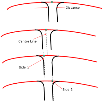


 Chordal
 True minimum radius
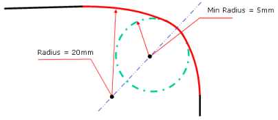
 Offset distance