Loft Dialog Box | ||||||
|
| |||||
- Guides
- Selects one or several curve elements as guides (V direction of the loft).
- Profiles
- Selects one or several curve elements as profile (U direction of the loft). Note: Only if the curve elements selected as guides and profiles lie in the corresponding direction U or V, the selection will be taken as valid input.
- Spine
- Selects one or several curve elements as spine curves.
The profiles/sections are driven along a spine curve. They lie upon a 2D plane which is perpendicular to the spine curve.
A separate spine curve can be selected for each edge of the lofted surface.
- Cleared: Uses an implicit spine curve which is calculated from the selected profiles and guides. For more information see Implicit spine.
- Selected: Selects a user-defined spine curve. For more information see User-defined spine.
Tolerance
- Intersection
- Defines the tolerance for the intersection points of guides and profiles. The intersection tolerance specifies the maximum distance to the support surfaces.
- Segment
- Defines the segment boundaries of the resulting surface at the intersection point between guide and profile according to the following criteria:
- If the value is exceeded at the point of intersection, the segment position results from the guide and profile curve intersection. The internal segmentation of the curves are ignored.
- lf the tolerance value is met at the point of intersection, the segment position result from a segment point of the selected curves.
Guide/Profile Segmentation
Influences the segmentation of the loft surface by the segmentation points of guide and profile curves. The following options are available:
- First
- Adopts the segmentation from the curve defined as first guide or profile. All other curves are ignored.
- Max.
- Adopts the segmentation from the guide or profile with the maximum number of segments.
- All
- Calculates the segmentation from the segment boundaries of all guides and profiles.
Guide/Profile Trim
Temporarily trims input curves that do not have coincident ends at their Start and/or End. The resultant surface is then created between temporary trimmed guides and profiles.
Guide/Profile Coupling
Influences the parametrization of the resultant surface by coupling the parametrization of the individual sets of curves (guides and profiles).
- None
- Calculates an automatic coupling.
- Segments
- Calculates the coupling using the number of segments contained within the set of curves (guides and profiles). This allows the user to re-parametrize according to the internal continuities.
- Cells
- Calculates the coupling using the number of cells (individual curves) defining the profiles and guides. This allows the user to re-parametrize according to the internal continuities.
- Bends
- Calculates the coupling using the number of bends (cells and segments) defining the profiles and guides. This allows the user to re-parametrize according to the internal continuities.
- G0, G1, G2
- Sets a continuity condition for the selected curves thus reducing the number of cells.
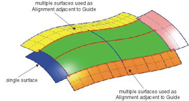
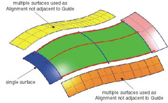
Guide/Profile Alignment
Influences the continuity condition of the selected Start and End curves for either guide or profile to an adjacent set of support surfaces.
- Support
- Defines a support for each side of the lofted surface.
- Start/End: G0, G1, G2, G3
- Sets a continuity condition for start and end curves. After creating the lofted surface, continuity manipulators are displayed at the support surfaces.
The images below demonstrate the acceptable configurations for the use of support surfaces for aligning guides and profiles.
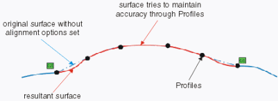
Alignment Influence
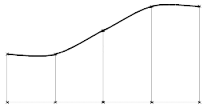
- Local
- The continuities assigned to a specific edge influence only to the local surface shape between the 1st and 2nd curve. The result attempts to pass through the guide and profile curves. The intent is to create a non-oscillating result.
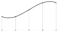
- Spread
- The continuities assigned to a specific edge influence the surface shape through all the selected internal guides and profiles. An oscillating result may be produced.

- Global
- The continuities assigned to a specific edge influence the entire surface shape. The result accuracy to the guide and profile curve inputs can be lost.
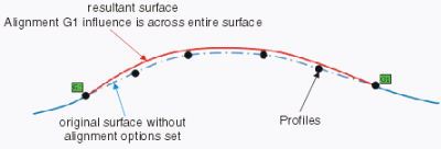
Note: The images are for demonstration only and show exaggerated conditions.
Adjust
Defines which input elements shall have priority for the surface calculation.
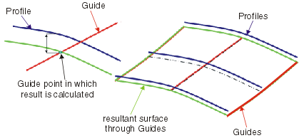
- Adjust to guide
- Defines the guides to have most influence on the result. The profiles are then used as guide to achieve the smoothest transition between the guides.
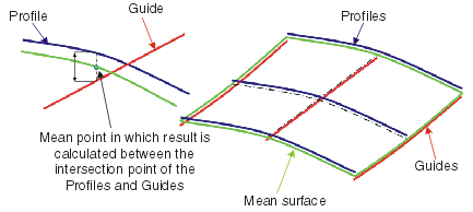
- Mean
- Calculates the result through the mean point between the intersection points of all profiles and guides to achieve the smoothest interpolation in both U and V direction.
- Adjust to profile
- Defines the profiles to have most influence on the result. The guides are then used as guide to achieve the smoothest transition of the result between the profiles.

Shape
Specifies the shape of the surface, i. e. the transition type between the individual selected profiles and guides.
 |  |
 |  |
More Info
Displays deviations and output results.
- Display
- Displays values in the work area.
- U+V
- Displays the UV vectors of curves and surfaces.
- Apply Modes
- Defines the update mode of the active feature while editing it.
- Dynamic
- Feature update occurs dynamically when moving handles or editing parameter values by sliders in the dialog box.
- Static
- Feature update occurs only after releasing the handle.
- Preview
- Displays a preview when geometry is modified by means of the handle and LMB pressed. The original geometry remains unchanged. Feature update occurs only after releasing the LMB.
- None
- Feature update occurs only after selecting Apply.
- Deviation
- Guides
- Displays the maximum deviation of the Guide curves from its true mathematical position
- Profiles
- Displays the maximum deviation of the Profile curves from its true mathematical position
- Support G0...G3
- Displays the maximum deviation of the result from the support surfaces at the surface limits defined by the first and last Guide and Profile curves.
- Output Result
- Max. order
- Indicates the maximum order of the result created in both U and V.
- Max. segments per cell
- Indicates the maximum number of segments created in U and V direction.
- No. of cells
- Indicates the number of cells created in the result.