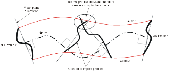
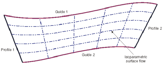
This section deals with the use of a user-defined spine.
The user-defined spine (check box Spine selected) must respect several criteria.
Construction of the spine curve
- Only connected curves are supported.
- Crossed curves (loops) are not supported.
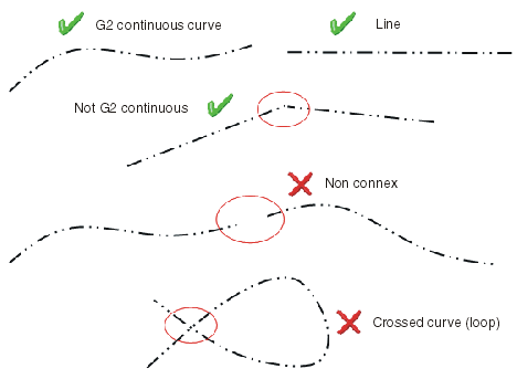
Length and position of the spine curve
- The spine curve must have at minimum the same length as the maximum distance between first and last selected profile.
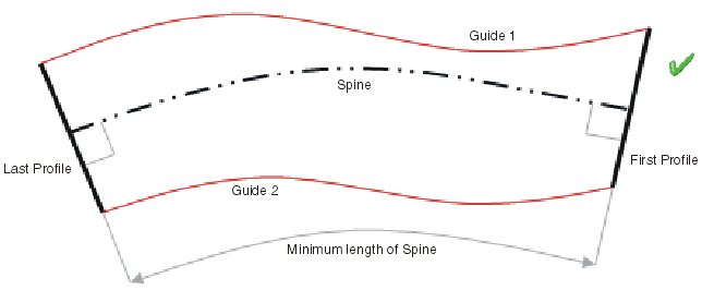
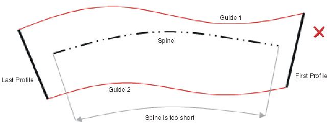
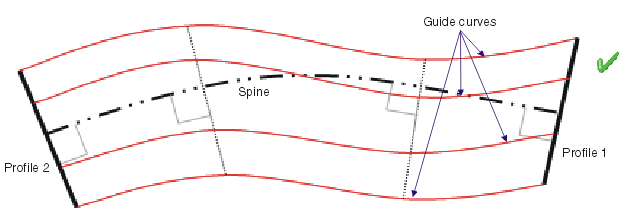
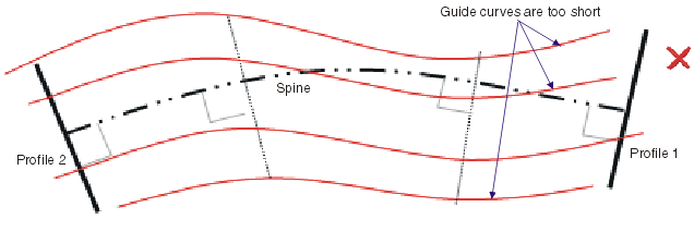
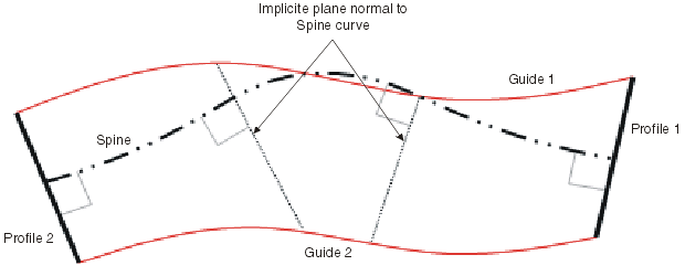
- The implicit plane created normal to the spine curve ensures that the profiles are driven perpendicularly along the spine curve. This plane MUST intersect all selected guide curves at all points. Therefore the spine curve positioning with respect to the guides and profiles is equally important.
Orientation of the spine curve
The selected profiles determine the shape of the lofted surface. It is required that the orientation of the spine curve in relation to the selected profiles is perpendicular.
- 2D Profiles (planar)
In many cases, the profiles will be created already in a 2D plane and in 3D space. Thus the spine orientation is automatically defined perpendicular to the plane lying on the section profile.
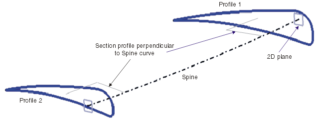
When only 2D profiles and no internal profiles are selected for the start and end of the lofted surface, the internal profiles are implicitly calculated and are perpendicularly swept along the spine curve.
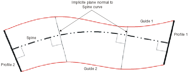
If the spine curve is then adjusted or a new spine is selected, it will influence the shape of the loft as the internal profiles are consequently adjusted.
Start and end of the spine curve must remain perpendicular to the selected 2D profile curves.
- 3D Profiles
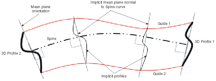
If it is not possible to use 2D profiles for start and end profiles, the input profiles are considered to be 3D. When a 3D curve is used as profile, the orientation of the spine curve is equally important.
- Internal Profiles
The spine curve must smoothly flow through each profile, such that an internal cusp in the loft result is not created.
