Selects a reference surface where the tube surface is to be positioned.
Create Tubing
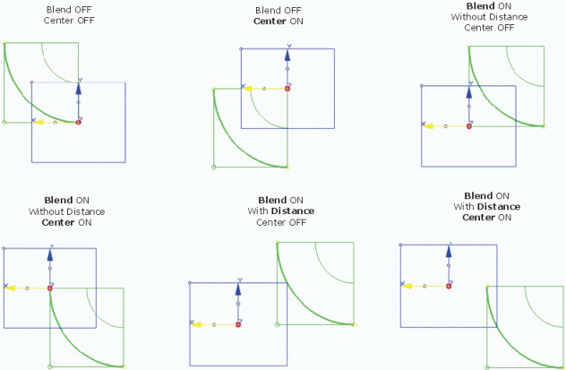
Center
Moves the center point of the tube surface as follows relating to the origin of the local coordinate system:
Cleared: The center point is moved along the y axis in a way that the surface touches the x axis.
Selected: The center point is lying on the x axis.
Radius
Defines the radius of the tube surface.
Blend
Moves the center point of the tube surface as follows relating to the origin of the local coordinate system:
Cleared: The center point is lying on the y axis.
Selected: The center point is moved along the x axis.
Distance = 0
Moves the center point so that the surface touches the y axis.
Distance > 0
Moves the center point so that the surface has the specified distance from the y axis.
Positioning the center point with Center, Blend, and Distance
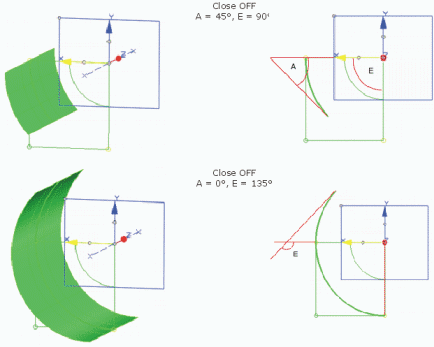
Close
Cleared: Creates an open tube surface.
As start and end angle, the angles between the cross tangents of the start and end edges of the tube surface and the X axis of the local coordinate system are measured.
If a reference surface is selected, the angle is measured relative to the tangent plane of the reference surface.
Start/End angle
Defines the angle of the open tube surface.
Only available if Close is inactive.
Selected: Creates a closed tube surface.
Open tube surface with different start and end angles
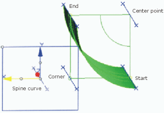
Create Curve
Creates curves in addition to the surface. These curves have the shape of the guide curves and run:
along the edge at the surface's start (Start),
along the edge at the surface's end (End),
through the surface's Center point (Center), or
through the theoretical corner (Corner).
Creation of additional curves
More Info
Displays deviations and output results.
Display
Displays values in the work area.
U+V
Displays the UV vectors of curves and surfaces.
MFT
Displays the local coordinate system for the moving frame type.
Apply Modes
Defines the update mode of the active feature while editing it.
Dynamic
Feature update occurs dynamically when moving handles or editing parameter
values by sliders in the dialog box.
This option is not available for each command.
Static
Feature update occurs only after releasing the handle.
Preview
Displays a preview when geometry is modified by means of the handle and LMB pressed. The
original geometry remains unchanged. Feature update occurs only
after releasing the LMB.
This option is not available for each command.
None
Feature update occurs only after selecting Apply.
Deviation
Circle
Deviation of the approximated Bezier surface from an exact circle. Can be influenced through the segmentation.
Reference
Deviation between the newly created tube and the reference geometry.
Output Result
Max. order
Indicates the maximum order of the result created in both U and V.
Max. segments per cell
Indicates the maximum number of segments created in U and V direction.
No. of cells
Indicates the number of cells created in the result.