Creating a Fillet Surface | |||
| |||
-
From the Surfacing section of the action bar, click
OmniFillet
 .
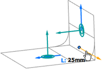
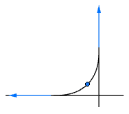
A fillet surface of the Chord Length type is created in the quadrant of the selected point positions.
.
A fillet surface of the Chord Length type is created in the quadrant of the selected point positions.
-
Select the
Fillet Type.
Option Description Radius

Defines the fillet surface by the radius. Chord Length

Defines the fillet surface by the chord length, that is the distance between both edges of the fillet surface lying on the support surfaces. The radius value changes accordingly. True Minimum Radius

Defines the fillet surface by a radius that is lower than the true minimum radius while keeping the continuities. The radius value reduces to keep G2 continuity. -
To change the radius, do one of the following:
- Click the Radius value in the panel.
- Click the value displayed in the work area.
- Drag the handles at the surface edges.

-
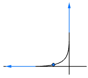
Click the invert normal handle.

The fillet surface is created in the quadrant to which the normals of the support surfaces are oriented.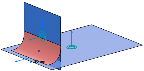
-
Change the continuity for Side A and Side
B.
Continuities G0 - G3 on Side A G0 G1 G2 G3 
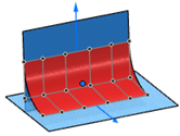
The order of the fillet surface adapts accordingly.
Tip: Select Modifiable  and
Orders Modifiable
and
Orders Modifiable
 in the Display section to
see the order of the fillet surface directly at the geometry.
in the Display section to
see the order of the fillet surface directly at the geometry. -
In the Explicit Controls section, modify the
Form Factor.
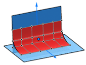
The Form Factor determines whether the created entity is more flat or more copped. The continuity to the support entity remains unchanged. You can also move the slider or drag the handle.
Form Factor 0.1 Form Factor 0.5 (default) Form Factor 0.9 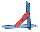
-
Modify the Form Bias in the same way.
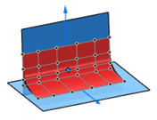
Form Bias is similar to Form Factor but the changes apply in an asymmetric way on each support. This allows you to create entities being closer to one of the two supports.

Form Bias 0.1 Form Bias 0.5 (default) Form Bias 0.9 
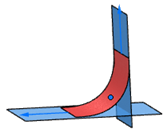
- Optional:
Modify the Limitation Ends to limit the resulting fillet
surface at its start or end. Do one of the
following:
- Click a value for Start or End in the Flow Control section of the panel.
- Use the sliders in the panel.
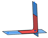
- Drag the handles at the surface edges.
Limitation Ends Before limiting the surface Dragging the handle to limit the surface at the start 
- Optional:
You can click Go back to
selection
 at any time to change the selection, define and use
selection sets, or to choose another mode in the selector
panel.
at any time to change the selection, define and use
selection sets, or to choose another mode in the selector
panel.
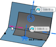
If the OmniFillet creation fails, the command locates up to five problematic areas on the input geometry. It encounters a gap that exceeds the topology tolerance when solving for a radius runout line. It highlights the area and displays the rounded gap value.
| Gap Detection | Zoomed In View |
|---|---|
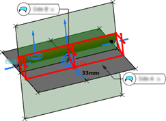 | 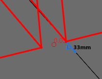 |
You can first correct the input surfaces using OmniMatch ![]() , for example, and then perform OmniFillet again.
, for example, and then perform OmniFillet again.