-
Select two surfaces and the spine curve.
You can also select two sets of surfaces and a set of curves. Alternatively,
you can use an automatically created spine curve (see
Use an Automatically Created Spine Curve).
-
From the Surfacing section of the action bar, click
OmniFillet
 .
.
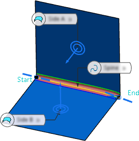
A fillet surface is created by two lengths in the quadrant of the
selected point positions (
Variable two Lengths type).
- Optional:
Click the invert normal handle to create the fillet surface in the quadrant to
which the normals of the support surfaces are oriented.
-
Change the continuity for Side A and Side
B (see Continuities G0 - G3 on Side A).
-
Define the Length values for the start and the end of
both sides. They determine the length between the spine and the radius runout
lines (RRLs) where the fillet touches the base surface
(see Fillet Surface Spine Type).
-
Click
 to edit the variable length functions for both sides from the start to the
end of the spine.
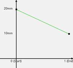
A 2D graph panel opens. Initially, the graphs show a straight
line between the start and the end values.
-
In the Side A/B Length Graph panel, you can:
- Select the graph you want to show and edit: Side A,
Side B, Side A and B,
Both Sides.
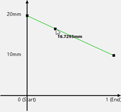
- Click Insert Point and select a position on the graph in the
panel or on the spine curve in the work area to add a point.
- Click
 to change it to
  . This links the
change of all values at both sides.
. This links the
change of all values at both sides.Note:
The number of points
on side A and B is always the same. With  , the value of
the points is also the same. With
  , you can
enter different values for side A and side B.
- Click Free or Constant to
define a free or a constant portion at this inner point.
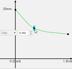
- Edit the point's position by means of the value box or by dragging the handle.
- Hover over a point on the graph or on the spine curve until it highlights, and press
Backspace to delete this point.
- Define the Length Shape Type:
Local, Smooth,
Global.
-
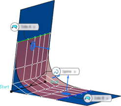
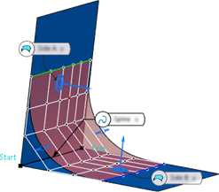
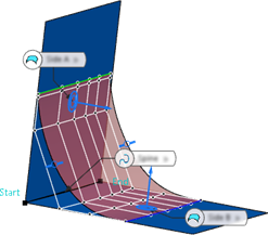
In the Explicit Controls section, define the
Tension values at the start and the end of both
sides. They determine how much the surface is pulled toward the
RRLs on each side.
| Tension at Side A for both
Start and End |
| Tension 0.1 |
Tension 1 (default) |
Tension 1.5 |
|
|
|
-
Click
 to edit the tension functions for both sides from the start to the end of the
spine.
A 2D graph panel opens. Initially, the graphs show a straight
line between the start and the end values.
-
In the Side A/B Tension Graph panel, you can insert, edit,
and delete points as described above for the length graph.
-
Define the boundary condition of the weight function for tensions at the start
and end of both sides. Select Free or
Constant for Flow A and
Flow B.
- Optional:
Modify the Limitation Ends to limit the resulting fillet
surface at its start or end (see Limitation Ends).
-
Define the Parameterization of the fillet surface.
- Optional:
You can click Go back to
selection
 at any time to change the selection, define and use
selection sets, or to choose another mode in the selector
panel.
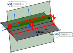
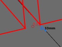
If the OmniFillet creation fails, the command locates up to five problematic areas on the input geometry. It encounters a gap that exceeds the topology tolerance when solving for a radius runout line. It highlights the area and displays the rounded gap value.
| Gap Detection | Zoomed In View |
|---|
|
|
You can first correct the input surfaces using OmniMatch  , for example, and then perform OmniFillet again.


![]() , for example, and then perform OmniFillet again.
, for example, and then perform OmniFillet again.


