Export of Mechanical Systems Design

3DEXPERIENCE mechanisms can be exported to V5 using the Downward Compatibility tool, although not all of the components of the mechanism can be exported.

To access the Downward Compatibility batch, from the Tools section of the action bar, click Utility. For more information, see Running the DownwardCompatibility Batch and About Downward Compatibility.

This page discusses:

3DEXPERIENCE to V5 Data Import Table

This table describes the export effect on mechanism entities that can be translated using the Downward Compatibility tool. See File Coexistence and Migration User's Guide for more information.

3DEXPERIENCE Data Type Export Effect
Mechanisms
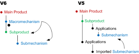
Mechanism representation under a root product (not flexible)Exported as mechanism. A mechanism is created under the Applications node.

See Structure Diagrams - 3DEXPERIENCE vs V5.

Partially defined mechanism Exported as mechanism but cannot be simulated in V5
Submechanism Exported as mechanism
Macro mechanism Not supported except a macro mechanism that assembles only one mechanism.
Commands
Command Partially supported as some joints cannot be assigned commands in V5. Potential orientation issues.

See Export Exceptions or Limitations for more information about commands.

Engineering ConnectionsPartially supported. Exported as V5 joints; V5 Assembly constraints are not created for geometry combinations that cannot be selected.

See 3DEXPERIENCE Engineering Connections vs V5 Assembly Constraints for more information.

Rigid Exported as rigid joint

All supports are permitted. However, the Fix Together relatively constraint is handled as a simple Fix Together in V5. The Fix Together relatively constraint does not exist in a V5 rigid joint.

Prismatic Exported as prismatic joint, except if the 3DEXPERIENCE engineering connection includes coincidence constraints and edge/line elements as supports.
Revolute Exported as revolute joint, except in the two following configurations:

  • if the 3DEXPERIENCE engineering connection includes a coincidence constraint and two edge/line elements as supports.
  • If the 3DEXPERIENCE engineering connection includes an offset constraint, a point and a face/plane elements as supports.

Spherical Partially supported. Exported as spherical joint if the spherical engineering connection includes a coincidence constraint and two points as supports. The curve as support is not supported.
Cylindrical Exported as cylindrical joint.

See Export Exceptions or Limitations for limitations on this type of joint.

Planar

Partially supported. Exported as planar joint, except if the 3DEXPERIENCE engineering connection includes an offset constraint and two face/plane elements as supports.

U Joint Not supported
Point Curve Exported as point curve joint.
Point Surface Exported as point surface joint
Roll Curve Exported as roll curve joint. A 3DEXPERIENCE command assigned to a Roll Curve is exported in V5. If there are two commands assigned to a 3DEXPERIENCE Roll Curve joint, only one command is created in V5.
Slide Curve Exported as slide curve joint. Assigning a command to a slide curve is not permitted in V5. Thus, if a command is assigned to a slide curve, it is not exported to V5.
Compound Engineering ConnectionsPartially supported.
GearExported as gear joint

See Export Exceptions or Limitations for limitations on this type of joint.

RackExported as rack joint

See Export Exceptions or Limitations for limitations on this type of joint.

CableExported as cable

See Export Exceptions or Limitations for limitations on this type of joint.

ScrewExported as a screw joint
Fixed Parts
Fixed Part Exported as fixed part. All supports are permitted. However the fix in space constraint will be handled as simple Fix as it does not exist for a V5 rigid joint.
Dressup
DressupExported as a dressup

Additional Information

This section lists the limitations and provides detailed structure diagrams.

Export Exceptions or Limitations

  • Compound Connections
Compound connections can be used to link the behavior of prismatic and revolute joints. In V5, the two elementary joints that participate in creating compound joints, including gear, rack and cable must share a common impacted product. A 3DEXPERIENCE compound joint that does not comply with this rule is exported as two elementary joints (a revolute joint and a prismatic joint).

  • Commands

In 3DEXPERIENCE, commands, can only be assigned to an engineering connection that includes a controlled constraint (available only for offset, curve, and angle constraints).

You can create more command types in 3DEXPERIENCE. If in 3DEXPERIENCE two commands are assigned to compound connections (gear, rack and cable), only one command is created in V5.

Assigning a command to a slide curve is not permitted in V5. Thus, if a command is assigned to a slide curve, it is not exported to V5.

A 3DEXPERIENCEcommand assigned to a roll curve is exported in V5. If there are two commands assigned to a 3DEXPERIENCE roll curve joint, only one command is created in V5.

The command orientation is exported for revolute, prismatic, cylindrical, or screw joints. For cylindrical and prismatic joints, specific situations arise where the command orientation cannot be kept during the export process.

  • 3DEXPERIENCE constraints

Free, symmetry, projection and user-defined supporting constraints involved in a mechanism are not exported when running the Downward Compatibility tool.

3DEXPERIENCE Engineering Connections vs V5 Assembly Constraints

A 3DEXPERIENCE engineering connection is a collection of one or more constraints that restrict the degrees of freedom between two components. A 3DEXPERIENCE engineering connection is defined by both a combination of constraints and a combination of geometry supports. As the geometry support combinations you can use to define engineering connections is wider in 3DEXPERIENCE, the table above lists in detailed the geometry selections that are allowed and supported when running the Downward Compatibility tool. In V5, joints use only the existing supporting geometries, thus no additional geometries are created.

Structure Diagrams - 3DEXPERIENCE vs V5

Example of a macro mechanism that assembles a single mechanism:

Downward Compatibility Migration Report: Example

A HTML report file is created at the end of the Downward Compatibility Export process. This file contains information that is specific to Mechanical Systems Design. Consider the following report message:

Section1
Introduces Downward Compatibility Batch information for Kinematics Mechanism Design export to V5.
Section 2
Provides a detailed status for each 3DEXPERIENCE engineering connection that is translated. For example:
 "Prismatic.1" joint creation is OK.
The V5 joint has been created in V5.
 "Fix.2" fixed part creation is OK.
The fixed part has been created in V5.
If an issue is detected during the export, the message displayed describes precisely the issue:
"Rigid.3" joint creation is KO. Contextual engineering connection is not supported.
The creation of the V5 joint failed because the contextual engineering connection type is not supported.
 "Rigid.3" joint creation is KO. Overloaded engineering connection is not supported.
The creation of the V5 joint failed because the overloaded engineering connection is not supported.
 "Prismatic.1" joint creation is KO. Some elementary constraints are not supported.
The V5 joint has not been created in V5 because some supporting elementary constraints are not supported.
"Gear.2" joint creation is KO. Gear is not a supported type.
The V5 joint has not been created in V5 because the engineering connection is not supported.
"Fix.3" fix creation is KO, Only one fixed part can be created on V5 side.
The V5 fixed part creation failed because a V5 fixed part has already been created in V5.
Section 3
Provides a detailed status for each 3DEXPERIENCE command that is translated. For example:
 "Command.1" command creation is OK.
"Command.2" command creation is KO.
Note: If a command assigned to a 3DEXPERIENCE engineering connection has not been correctly translated in V5, no command is created and no report message is displayed.
Section 4
Provides a summary of the successful export operations for all engineering connections and commands in the mechanism. As an example:
 Engineering connection conversion status: = 1 OK | 1 KO - Command conversion status: = 1 OK | 0 KO
Section 5
Gives a global status for the mechanism. It can also includes information about the limitations related to the submechanisms' conversion.
The mechanism contains one or several submechanisms that will not be converted to V5.
V6 Mechanism Mechanism_with_prismatic : has been converted partially to a V5 Mechanism.