Creating a Panel Wall | ||||
|
| |||
-
From the Building section of the action bar, click Panel Wall
 .
.
-
In the
3D area,
click the building face or space wall where you want to create the panel wall.
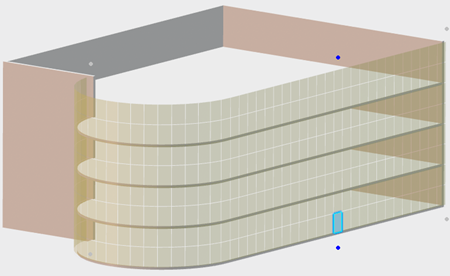
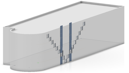
The system displays a jig that shows all the possible locations where you can place panels.
Tip: The system also displays three possible alignments for the panel wall. These alignments are indicated by dots on opposite sides of the center, right, and left of the selected faces. The blue dots indicate the current alignment. The panel wall alignment helps to keep the placed panels in the required position when the size of the panel wall changes. You can change the panel wall alignment after placing one or more panels. When you hover the mouse over a possible location, the system highlights the location.
Note: For surface driven panels, if full panels do not fit in the boundary of the panel wall, you can place clipped panels in the panel wall. Click a green jig in the 3D area to place a clipped panel. -
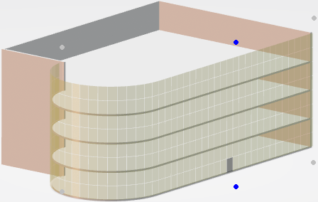
To place the first panel and to select the panel wall alignment,
click the appropriate highlighted location.
The system displays a panel wall in the selected location on the jig.
Tips: To turn off the jig display, click Show Jig  . Turning off the jig display is especially useful
when editing or repositioning placed panels. Later, you can click the
Show Jig toggle to turn on the jig display.
Turning on the jig is especially useful when placing new panels.
. Turning off the jig display is especially useful
when editing or repositioning placed panels. Later, you can click the
Show Jig toggle to turn on the jig display.
Turning on the jig is especially useful when placing new panels. -
To search and select a Panel Wall feature, click Search
Component
 ,
select the component, and double click to place it.
Notes:
,
select the component, and double click to place it.
Notes:- When you click Search Component , it searches for the components in a collaborative space named CCT Components Library, if it exists. To avoid unwanted matches with duplicates of components already inserted in buildings, create a collaborative space named CCT Components Library.
- Import the building components into CCT Components Library using
Import Building Components
 .
. - You can also search the components from the general search box. In this case, all the collaborative spaces accessible to you are searched.
- You can refine the search results using 6W tags, bookmarks, and stored queries.
-
In the
Panel Wall dialog box:
-
In
Single
 , select a pattern.
Option Description Single
Creates a single panel of the specified type and dimensions. All in a Row 
Creates a row of panels of the specified type and dimensions. Above and Below 
Creates a column of panels of the specified type and dimensions. All in Panel Wall 
Creates panels of the specified type and dimensions at all possible locations over the entire panel wall. -
Select a Panel Definition.
The panel definitions beginning with G are glazed panels whereas those beginning with S are solid.
Note: If you create additional panel types as adaptive building components, the system includes your panel types in the Panel Definition list. For example, if you create S-Granite as an adaptive building component, the system includes S-Granite in the Panel Definition list. -
Enter the values for the dimensions associated with your
Panel Definition selection.
Tip: To force a reimport of the component and update the list of panel types, Ctrl + select the panel definition in the Panel Wall dialog box.
-
In
Single
-
In the 3D area select the panel locations.
-
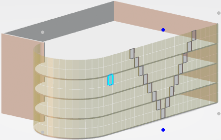
From the possible panel locations, click where you want to place the
panel or panels.
For example, with the Panel Definition G-Simple and the pattern Single, click a selection of panels.The preview in the 3D area displays your panel selection in black.
-
To see a preview of the panels with your Panel Definition selection, in
the dialog box, click Create Panel
 .
.
-
From the possible panel locations, click where you want to place the
panel or panels.
-
To change:
-
The panel definition, in the dialog box, select another
Panel Definition.
For example, switch from Glazed Configurable Panel (G-Config) to Solid Simple (S-Simple).
-
The panel pattern, select another pattern from the pattern
list.
For example, to change from single panels to columns select Above and Below.
-
One or more dimensions, enter new values for the dimensions.
Notes: The available dimension options change with each different Panel Definition selection.
When you change dimension or the Panel Definition, the system updates and redisplays the jig.
-
In the
3D area,
in the jig, from the possible panel locations, click where you want to place
the new panels.
For example, select two rows of cells one on either side of the center of the panel wall.
-
To see a preview of the panels with your new Panel Definition
selection, in the dialog box, click
Create Panel
.
Note: When you switch the Panel Definition or change the panel dimensions, the system commits the panels that are in the panel wall preview.They system adds your changes to the panel wall preview without changing the previous panels.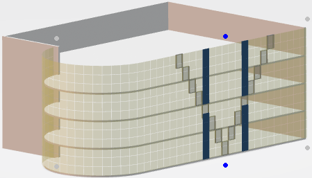
-
The panel definition, in the dialog box, select another
Panel Definition.
-
To change one or more panels to the current Panel Definition or
dimensions:
- Ctrl + select the panels you want to change.
- Right-click and from the context menu, select Replace panel.
For example, use the Replace Panel command to change two simple glazed panels to glazed panels with three vertical panels and three horizontal panels, that is, G-3V_XHSE with 3 for Number of Panels.
-
To change the panel wall alignment, click a gray alignment dot.
For example, to change from center-alignment to left-alignment, click the gray alignment dots on the left.The alignment changes and the gray dots change to blue. If the building length changes later, the pattern left aligns.
-
In the dialog box, click
 .
.
The system creates the panel wall. In the tree, the system displays the panel wall in the active product. For building, elevator, and stairwell panel walls, the system lists the panel wall under Shell and Core. For a space panel wall, the system lists the panel wall in the active story where the space is located. The listing includes each panel in the wall.
To edit the panel wall in the tree, select the entire panel wall (that is, Panel Wall just
below the Panel Wall node), right-click, and from the context toolbar, click Edit Feature
 .
.
To edit any individual panel or panels, in the tree, select the panels, right-click, and from the context toolbar, click Edit Feature
.