-
Select geometric elements from two different 3D parts.
-
In the context
toolbar, click
Select
 . .
-
Select the type of constraint you want to apply from the vertical toolbar.
The following geometric relationships and 3D dimensions are available:

|
Fix
|

|
Contact
|

|
Perpendicularity
|

|
Parallelism
|

|
Angle
|

|
Distance
(or offset)
|

|
Coincidence
|
A tooltip upper right informs you that an engineering connection is created, and the corresponding constraint symbol displayed. In the image below, a Contact constraint symbol  . 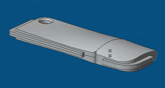 - If an engineering connection exists between the two 3D parts, the new 3D constraint is added to the existing engineering connection.
- If the new 3D constraint is redundant and over defines the product, it is not created.
- Optional:
To edit the constraint you have just
created, click the constraint symbol and do one or more of the following:
- Select the constraint mode: driving
 , measured , measured
 or controlled
 . .
- Select the constraint orientation
for one or both 3D parts: undefined
 , same , same
 , opposite , opposite
 or parallel or parallel
 . .
- Select
De-activate
 to de-activate the 3D constraint. to de-activate the 3D constraint.
- For angle and distance constraints,
change the value.
|
