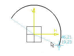
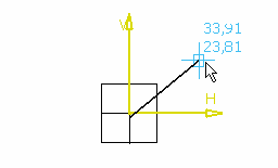
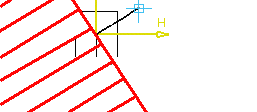
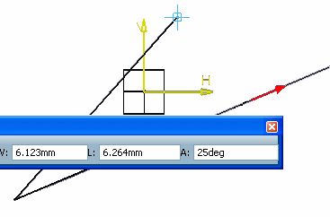
There are a few things that you need to know when using SmartPick with existing geometry.
Reference Geometry
SmartPick finds out geometrical specifications according to
geometrical elements that already exist in a sketch.
You will only detect geometrical specifications according to the
current sketch elements that are visible in the 3D window in which
the pointer is positioned. You will not need to perform any
interaction and you will be returned a visual feedback as shown
below in a non exhaustive way:
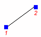
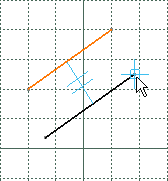
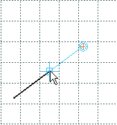
- Parallel (two lines)
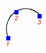
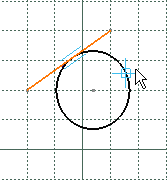
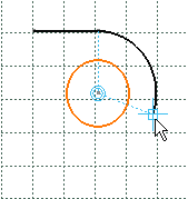
- Tangent (a line and a circle)
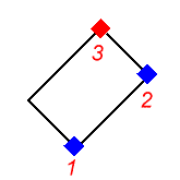
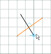
- Perpendicular (two lines)
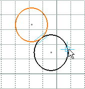
- Tangent (two circles)
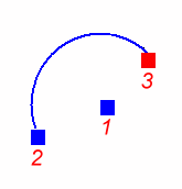
- Concentric (a circle and an arc)
- Parallel (two lines)
As you will see when using SmartPick, snapping ambiguities
currently occur. Besides, the dimensional specifications of a part
often depend on technological specifications.
These dimensional specifications are defined as the part is being
designed, they depend on the current application area and are, as a
result, very hard to guess for the SmartPick tool.
In order to solve these ambiguities, SmartPick classifies possible
snapping according to the geometric constraints that are associated
to these snapping. As such, a given pointer positioning will be only
assigned one snapping. Unfortunately, this classification cannot be
modified. It is provided in the table below.
| Constraints Decreasing Priority Order |
|---|
| 1. | Point-to-point coincidence |
| 2. | Point-to-extremity point coincidence |
| 3. | Point-to-noticeable point coincidence (for example, the midpoint of a line) |
| 4. | Curve-to-curve tangency |
| 5. | Horizontal or vertical line, or else a quarter of an arc of a circle |
| 6. | Parallelism
|
| 7. | Perpendicular curves |
| 8. | Point-to-curve coincidence |
| 9. | Curve-to-curve coincidence or point to curve support coincidence |
| 10. | Point on a perpendicular line through a line end point |
| 11. | Point at a vertical position |
| 12. | Point at a horizontal position |
Moreover, to remove ambiguity during the creation of elements, the
three options which are parallelism, perpendicular and tangency can
be activated independently from each other. See SmartPick options
in the Customizing section of this guide.
In addition to this classification, when several snappings are
possible for a given type of geometric constraints, SmartPick takes
into account the distance between the snapped pointer and the
geometrical element according to which the snapping is possible. In
this case, SmartPick snaps to the nearest element.
Nevertheless, there are some cases when SmartPick does not let
dimensioning as desired without additional interactions. This is
why SmartPick manages two means for applying a particular snapping
relatively to the geometrical elements.
Forcing the Snapping
SmartPick lets forcing the snapping on a given geometrical
element using one of the following:
- The context menu
- The Ctrl key
context menu:SmartPick allows forcing the snapping on a given geometrical
element using the context menu. You will avoid ambiguities
linked to the automatic detection of elements in the current 3D
viewpoint by forcing:
Snapping detected at a distance: parallel, perpendicular,
concentric, tangency and curve (line/circle) that goes through a
point.
At a distance means that these constraints are detected even
though the pointer is not positioned on the reference element.
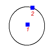
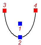
Snapping at a given position that is relative to a geometrical element: line midpoint, circle center.
At a given position means that both degrees of freedom are locked.
The context menu is therefore available when right-clicking most
Sketcher geometrical elements. Of course, the contents of the
context menu depends of the element that is being currently
created. This context menu can be made of the below four
sub-parts:
- Option that belongs to the Base Infrastructure app.
- Snapping the characteristic point that is being manipulated (see From scratch paragraph and table below).
- Snapping the geometrical element that is being created (see table below).
- Managing the parameters that are associated to the geometrical
element that is being sketched.
Deactivating Snapping
:Any snapping that is imposed via the context menu can be
deactivated. To do this, right-click in the 3D window background
and select Reset.
The table below lists the constraints that can be detected when
snapping characteristic points which are being manipulated,
relatively to existing geometrical elements, and thanks to the
context menu.
| Popped-up Geometry | Available Snapping |
|---|
| Line
| Line midpoint
|
| Circle
| Circle center
|
| Ellipse
| Ellipse center
|
| Curve
| Nearest end point
|
The table below indicates the possible snapping for geometrical
elements which are being created, relatively to existing geometry
and thanks to the context menu.
| Element currently created | |
|
|
| External Geometry => | | Point
| Line | Ellipse |
| Point
|

|

|   |
| Line | Midpoint
Nearest end point
|    |  |
| Circle
| Center
Nearest end point
|   |   |
| Ellipse | Center
Nearest end point
|   | No |
| Conic
| No
|   | No |
| Spline
| No
|   | No |
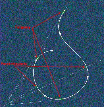
Example of snapping possibilities :In the example below, you can see the various snapping
possibilities for a line that is being created (dotted lines in the
example) relatively to the existing spline: 3 tangency
possibilities and 2 perpendicularity possibilities. The point you
right-click to display the context menu is used to determine
which option will be offered in the context menu. So depending
on where you click, you will not be offered the same options.
Note that the software takes into account what has already been specified (in this example, the first point of the line) to offer the various snapping options. For this reason, depending on the first point of the geometrical element that is being created, there may be cases in which no solution can be found or in which the solution offered does not correspond to what you want. In such a case, try to right-click before and/or after the point you want the software to choose. If you try both ways, one solution at least should be found.
Ctrl Key :
SmartPick also allows forcing the current snapping on an element
using the Ctrl key:
- You can force SmartPick to remain snapped on an element whatever
the position of the pointer. In order to do this, press the
Ctrl key while the geometrical snapping you want to
force is active (the element may be highlighted and symbols may
appear). Keep the Ctrl key pressed.
- This functionality is efficient if once the Ctrl key is
pressed you can still move the pointer. In other words,
Ctrl has no effect if the current snapping inhibits both
degrees of freedom. This is often the case when given snapping
combinations are possible (for example at the intersection of two
lines) or when the pointer is close to a given point (explicit or
implicit as for example the midpoint of a segment).
- The Ctrl key is very useful when the sketch includes
many geometrical elements because SmartPick takes into account the
distance between the pointer and the geometrical element.
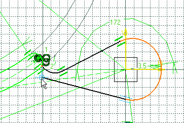
- This is the zone in which the line-circle tangency snapping (due to
the circle proximity) has the first priority.
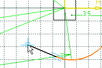
Apart from this zone, either the tangency snapping is meaningless
or it interferes with closest geometries or still with possible
constraints that are assigned higher priorities (see table).
Deactivating SmartPick
:If SmartPick cannot solve an ambiguity and returns a snapping that
you are not satisfied with, you can de-activate SmartPick assistant
by pressing the Shift key.
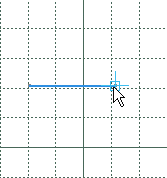
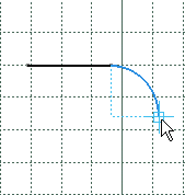
Detecting Internal Geometry Characteristics
:Certain geometrical elements are assigned internal peculiar
geometrical characteristics. For example and as shown below, this
is the case for horizontal/vertical lines and for quarters of arcs
of circles. When such an internal specification is found out by
SmartPick, the color of the currently created geometrical element
becomes blue.
 ), and others with partial freedom (only
one degree of freedom is available
  ).
).