Creating a Breakout | |||||
|
| ||||
-
Click as many points as required to create the profile, and click the first
point to close the profile or double-click to end the profile creation.
 :
Lets you replace the breakout profile.
:
Lets you replace the breakout profile. :
Changes the visualization to a view that is normal to the breakout back
plane.
:
Changes the visualization to a view that is normal to the breakout back
plane.Tip: You can also create the profile in the Breakout dialog box. 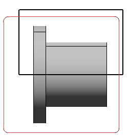
Note: The 3D viewer lets you manipulate the 3D part. It also lets you visualize a view plane or a 3D point and use them to define the depth of the breakout. -
Perform either of the following operations:
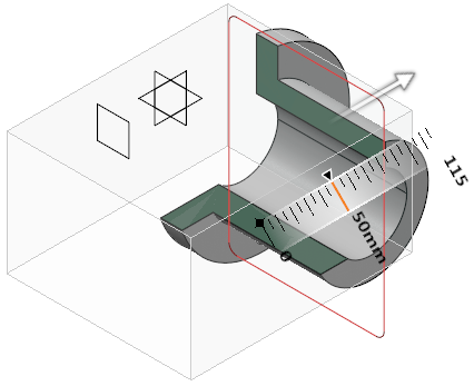
- In the 3D viewer, drag the arrow to the required location. The breakout is not associative with any element.
- In the 3D viewer, perform the following operation:
- Click the arrow to activate the reference element selection.
- Select a face, a circular edge, an axis system, a 3D point, or a 3D plane as a reference element to define the depth of the breakout.
- Under Parameters, in the
Offset or X box,
enter a value.
You can also define the depth by dragging the arrow.
You can select any of the following for plane translation during reference selection:
- Translate plane to geometry
 : Moves the plane according to the selected element. By
default, this option is selected.
: Moves the plane according to the selected element. By
default, this option is selected. - Translate plane to bounding box
 : Lets you select a plane using the bounding box of the
selected element. The selected face is highlighted with cyan
color.
: Lets you select a plane using the bounding box of the
selected element. The selected face is highlighted with cyan
color. - Translate plane along main axis
 : Lets you translate the plane along the main axis.
- Optional:
Under Display, click the following options to change the
visualization accordingly:
- Clipping tool:
- Display background and clipping tool
 : Shows the 3D object and the clipping tool.
 - Display clipped background and clipping tool
 : Shows the clipped 3D object and the clipping tool.
 - Display clipping tool
 : Shows only the clipping tool.
- Display background and clipping tool
- Immersive view
 : The 3D
part appears in a separate window. You can access the various display options to
change the visualization. Click to
switch back to the Clipping dialog box.
: The 3D
part appears in a separate window. You can access the various display options to
change the visualization. Click to
switch back to the Clipping dialog box. - Transparency: Modifies the transparency of the clipping tool. By default, the value is 200.
- Turn viewpoint: Turns the viewpoint of the 3D object
to Iso, Front, Rear, Left, Right, Top, or Bottom.
- With respect to view plane: The viewpoint to be turned is with respect to the view plane. In this case, the 2D layout plane is used as the front view.
- According to standard orientation: The viewpoint to be turned is with respect to the standard orientation.
The breakout is created.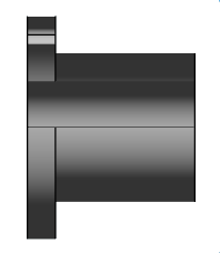
- Clipping tool: