In the Drawingtab, from the View Layout
section of the action bar, select New View.
Create a view.
For more information, see 3D Modeling: Mechanical
Systems: Drafting User's Guide: Creating Views: Creating
Views.
From the View Layout section of the action bar, select Transfer Views in a
Layout.
Select the created view, either from the tree or
from the drawing sheet.
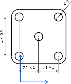
The view as seen in the drawing sheet
In the View Conversion Options dialog box, select the required
conversion options from
the following:
Elements to Generate: Generates the following
elements apart from the geometry itself. Select the required elements from
the following:
Dress-Up
Annotations
Dimensions
Convert black to white: Generates the elements
(dress-up, annotations, dimensions, and geometry) selected above using the
white color in the layout if they are black in the drawing for better visual
contrast.
Create end points: Creates points at the end of
geometrical items which do not have any. Leaving this option unselected
reduces the size of 2D layout data and increases performance.
Click OK.
In the Layouttab, select the empty sheet either
from the tree or from the 3D area.
The selected view is transferred from the drawing sheet to the
layout view and is listed in the tree.The view as seen in the layout sheet after transferring (In the
View Conversion Options dialog box, the
Dimensions check box is selected)
Click OK.
Switch to the 3D shape tab.
The selected objects are now projected in the 3D area.The view as seen in the 3D area
 .
.
 .
.