Creating Arrow Markers

You can create 3D arrow markers of required shapes and orientation, and position them with ease.


Before you begin:
  • Open an existing review or create a new review.
  • Clear the Snap 3D Arrow (Shift toggle) check box available at Me > Preferences > All Preferences > Social and Collaborative > Global Design Management > Design Review > Marker. If you select this check box, the snapping behavior using Shift is toggled.
See Also
Modifying Marker Shape and Position
Modifying Graphical Properties
  1. From the Review section of the action bar, click Arrow or Left Right Arrow .
  2. Click on a geometry or in the 3D area to create the marker.

    The marker is created as follows:

    Selected Element Marker Creation
    No selection The arrow is created horizontal, pointing towards left.

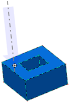
    Planar surface The arrow is created perpendicular to the surface at the selected point.

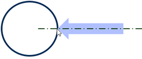
    Circular curve The arrow is created perpendicular to a line which is tangent to the circle at the selected point.

    If you press Shift, the arrow is previewed perpendicular to the circle's plane, pointing the center of the circle.


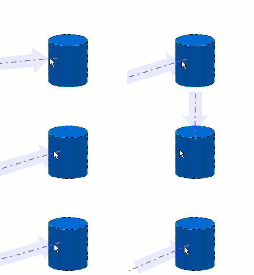
    Revolution surfaces The arrow is created perpendicular to the plane which is tangent to the revolution surface at the selected point.

    If you press Shift, the arrow is previewed perpendicular to the plane of the circular curve, pointing the center of the circle.

    In case of more than one circular curve are available, as in case of cylinders, the curve closer to the pointer is taken into account.


    Tip: During marker creation, you can also drag the marker to create it of required size and orientation. While dragging, you can anytime press Shift to snap the arrow to its axis. The axis of the arrow is positioned according to the pointed geometry, as described in the above table.

  3. Use the different manipulators to modify the shape, position, and orientation of the marker.
    For more information, see Modifying Marker Shape and Position.
  4. To create a link with an object:
    1. Right-click the arrow marker; and select Associated object > Begin > Create.
    2. Select an object from the tree.
  5. To replace or delete one or two links:
    1. Right-click the arrow marker, and select Associated object > Begin/End > Replace.
    2. Select another object to create a new link.
    3. Right-click the arrow marker, and select Associated object > Begin/End > Delete.

    When you create an arrow, you must associate extremity points before you perform create, replace, or delete operations. You can associate 3D arrow markers to one or two objects. Each extremity of the arrow is associated to a single object.

Notes:
  • When you move a geometry to which a marker is linked, the marker moves with the geometry.
  • When you switch a geometry to which a marker is linked to no-show space, the marker is not displayed. (Note: In the tree, you must select the Product and not the 3D Shape.) When the marker is set to no-show, switching the linked geometry to show state will not alter the no-show state of the marker.

    When the linked geometry is not loaded in the session, the marker is not displayed.

  • The markers linked to an unloaded object are not displayed in the 3D area. However, these markers are displayed in the tree with the mask. For a marker with multiple leaders, only the leader linking to the unloaded object is hidden. The marker is hidden only when all of its linked objects are unloaded.