About Composite Shell Sections | ||||
|
| |||
The makeup of a composite section is defined in the Composites Design app.
The support that you select for the composite shell section must already have composite parameters associated with it. In addition, the material applied to the support must have the Isotropic Elasticity or Lamina Elasticity option defined within the Simulation domain.
Composite shells are available only when you have the appropriate role.
Composite Grids and Zones
The Composites Design app lets you define composite layups using grids or zones. Grids are typically used for aerospace structures that contain a large number of regions with varying thickness, known as cells. You can define cells using a thickness law and a stacking sequence; the latter allows you to specify the layer order in the laminate. Composites Designgenerates cells automatically and allows you to manage complex composite designs.
In contrast, you use zones when your structure contains only a few regions with varying thickness. You can define zones using only a thickness law, and you cannot specify the layer order in the laminate.
Core Sampling
The core sampling operation extracts the composite information (defined as grid, zone, or ply) and associates it with the core sampling points on the mesh. The core sampling depth must account for the gap between the core sampling points on the mesh and the geometry. If the model definition includes cores, specify a depth that is at least the maximum thickness of the cores. By default, the depth is approximately the maximum element edge length.
The core sampling points are at the center of the faces of the shell elements. The arrow in
the image indicates the depth (the green line is the mesh surface, and the red curve is the
geometry; in this example, the depth accounts for the sag between the geometry and the mesh). 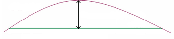
Dummy Plies
You can use dummy plies to account for nonstructural plies that are not included in the composite definition. If the thickness derived from the composite definition is less than the true thickness of the part, contact detection in the simulation might be inaccurate. You can use dummy plies to account for the difference in thickness between the composite definition and the part.