-
From the Properties
section of the action
bar, click Composite Shell Section
 . .
- Optional:
Enter a descriptive
Name.
-
Select a geometry support.
A composite shell section must be applied to one or more surface geometries
with associated composite parameters. You can also use geometry from an ordered
geometric set. Note:
The support for each composite shell section must include a
consistent use of grid-, ply-, or zone-based (grid, virtual stacking grid,
plies, ply groups, cores, sequences of plies) items to be consistent with
the sections defined in the Composites Design
app.
-
To define the support for the Composites definition, do
one of the following:
- Select the support directly from the 3D area or the tree.
- Set the selection method to Grid
 , and select one of the composite grids defined
using a grid or virtual stacking grid. , and select one of the composite grids defined
using a grid or virtual stacking grid.
- Set the selection method to All plies
 or All zones
 to have the app automatically select all plies in the composite stacking or all zones in
the composite preliminary design associated with the selected geometry,
respectively.
to have the app automatically select all plies in the composite stacking or all zones in
the composite preliminary design associated with the selected geometry,
respectively.
- Set the selection method to Ply
 or
Zone or
Zone
 to
select specific sequences of plies in the stacking or specific zone groups
in the composite preliminary design, respectively. to
select specific sequences of plies in the stacking or specific zone groups
in the composite preliminary design, respectively.
If you selected Grid, Ply,
or Zonea selection tree appears, containing all plies or zone groups associated
with the selected geometry.
- Optional:
Adjust the core sampling depth, which is the distance tolerance the app uses
while searching for composite geometry to associate with the core sampling
points on the mesh. You can edit the value directly, or you can use the
interactive depth visualization tool:
-
Click Visualize core sampling depth.
The depth visualization tool appears on one of the elements in
the support.
- Optional:
Drag the ends of the depth indicator to change the core sampling depth
interactively.
-
Press Escape to return to the
Composite Shell Section dialog box.
If you edit the depth value directly in the dialog box after you have
displayed the core sampling depth, the depth visualization updates
accordingly.
-
For composites defined by plies, specify the following:
-
Optional: Select Compute fiber orientations from
manufacturing parameters.
For selected plies, if you have also defined producibility in the Composites Design
app, the app computes the fiber orientations using the manufacturing
core sampling algorithm. This computation accounts for the ply
stacking and draping defined in Composites Design.
If you have not defined producibility or you do not use this
computation option, the app computes the fiber orientations using a
geometric core sampling algorithm.
-
Optional: Select Cut-pieces to
include cut-pieces, defined in the Composites Design
app, in the calculation of the composite supports.
Cut-pieces represent a single ply from the manufacturing point of
view. They also indicate the presence of subply staggering and
overlapping.
- Optional:
If your composite is defined by zones, select Apply
symmetry.
Choose this option to indicate that the selected zones or plies are symmetric
about the geometry support.
-
Select Include nonstructural ply thickness to create
dummy plies to account for the thickness of nonstructural plies.
-
From the Position options, select one of the
following options for the location of the dummy plies.
| Option |
Description |
| Top only |
Adds one dummy ply to the composite at the top of
the layup. The thickness of this ply is equal to
the total of the thicknesses of all nonstructural
plies in the layup. |
| Bottom only |
Adds one dummy ply to the composite at the bottom
of the layup. The thickness of this ply is equal
to the total of the thicknesses of all
nonstructural plies in the layup. |
| Top and Bottom |
Adds two dummy plies, one at the top and another
at the bottom of the layup. The thickness of each
dummy ply is equal to half the total of the
thicknesses of all nonstructural plies in the
layup. |
-
Assign a Material for the dummy plies. Because
these are nonstructural plies, choose a material with properties that
have negligible mechanical effects in the simulation.
-
Specify the Ply angle to assign to the dummy
plies.
-
Do one of the following:
- If the response of the shell is linear elastic, select
Integrate section before analysis to calculate
the cross-sectional behavior by linear moment-bending and force-membrane
strain relationships.
- If the shell material includes nonlinear behavior, clear
Integrate section before analysis to calculate
the cross-sectional behavior by numerical integration through the shell
thickness.
-
From the Integration scheme options, select
Simpson's rule or Gauss
quadrature.
If you require results output on the composite shell surfaces, use integration
based on Simpson's rule. Otherwise, use Gauss quadrature integration.
-
Enter a value for the number of Integration points to
be used through the composite shell section.
The default is
three points if you use Simpson's rule and two points if you use Gauss
quadrature.
-
Enter a value for the number of Field points to be used
through the composite shell section.
This value is used for the temperature or field points. By default it matches
the number of integration points.
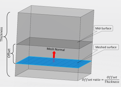
-
From the Offset definition options, choose one of the
following:
| Option | Description |
|---|
| Automatic |
The app calculates the offset automatically by taking into account
the defined ply thicknesses and stacking directions. |
| None |
The geometry support for the composite shell and the center of the
shell thickness are coincident. |
| Specify distance |
Distance (measured along the positive normal direction of the shell)
between the geometry support and the center of the composite shell
thickness. |
| Ratio of thickness |
Distance specified as a fraction of the shell thickness (and
measured along the positive normal direction of the shell) between the
geometry support and the center of the composite shell
thickness. |
| Top surface |
The geometry support for the composite shell represents the top
surface of the shell. |
| Bottom surface |
The geometry support for the composite shell represents the bottom
surface of the shell. |
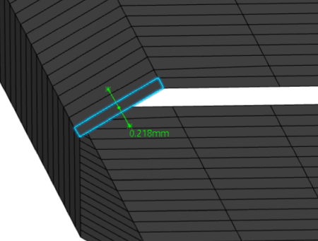
| From solid |
Offset value is extracted from the solid geometry that you select,
as shown in the image below.
|
-
Click OK.
|