Define an Operation Position Using Cumulative Snap | ||||||
|
| |||||
-
Right-click the general operation in the tree and select .
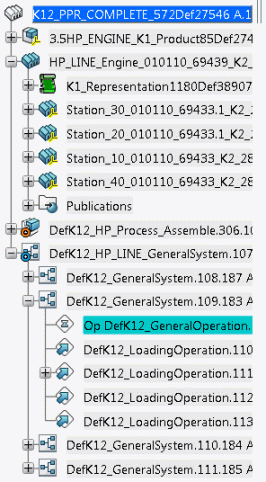
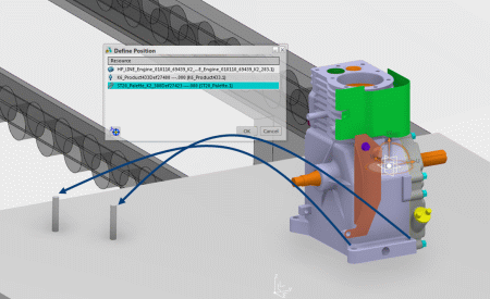
The Define Position dialog box appears.
-
Select the palette resource.
The image below shows how the two holes on the base of the engine assembly are to be positioned on the two locating pins.
-
Use the Robot to move the engine so that it lies on the palette, and is positioned
using the locating pins.
The third constraint is defined. The second and third constraints are also respected.
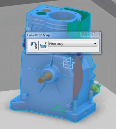
Alternatively, you can use the Snap
Product on Resource
 command.
command.- The local mode enables you to move the Robot separately from the assembled product, allowing precise positionning of the Robot origin.
- The global mode enables you to move the Robot and the assembled product allowing precise positioning relative to a resource.
The Snap Product on Resource
command
inhérits the same capablities as the Snap command. For more
information, see Simulation:Virtual Factory: Plant Layout Design: Smart Snapping
Resources: Snapping Products or Resources.
Note:
When using the
Cumulative Snap
 or Snap
Product on Resource
commands,
only the assembled product moves while the resources remain fixed. It is only at the end
of the action that the resources recover their potential position relative to the
assembled product.
or Snap
Product on Resource
commands,
only the assembled product moves while the resources remain fixed. It is only at the end
of the action that the resources recover their potential position relative to the
assembled product.
or Snap
Product on Resource
commands,
only the assembled product moves while the resources remain fixed. It is only at the end
of the action that the resources recover their potential position relative to the
assembled product.