Standard Gate
This section describes the standard Gate types.
The standard Gates are supplied as 3D Parts in a catalog located in ..\startup\components\MtdCatalog\GateGateCatalog.3dxml
- Gate in Runner Creation
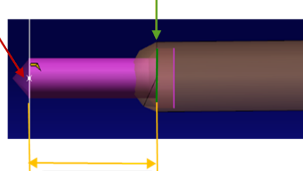
- Among other information, the Gate associated to the Injection Point contains information used to create Runners: When you create a Runner on an Injection Point, the Runner is relimited between the Injection Point (shown by the red arrow) and the Runner start plane (shown by the green arrow). This distance is represented by the LToLimitRunner invisible parameter (shown by the yellow double-head arrow), and may vary with the type of Gate.

- Direct Gate
- The Direct Gate is the default Gate type during creation of an Injection Point.
- In a Direct Gate,
the sprue serves as the Gate.
- The Gate is placed on the top side of the product.
- This type of Gate can only produce one part per shot.
- The molding cost is low because the material from the Runner is eliminated and the injection pressure is reduced by the direct
cavity filling. The cost of the Tool is also low because of the simple mold structure.
- This Gate has no subtypes.
- The Gate has no parameters; its shape is the same as the Runner (equivalent to LToLimitRunner=0).
- Film Gate
- A Film Gate is used typically for thin and flat Plate parts.

- Fan Gate
- A Fan Gate is used typically for large and flat plate parts.

- Side Gate
- A Side Gate is used typically for Tool structures with two or more cavities.
- The Gate is placed at the side of the plastic part.
- There are two types of Side Gate:
- Side Round Gate:

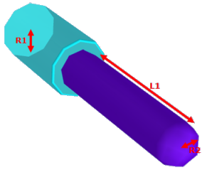
The Side
Round Gate is defined as a cylinder with the following
parameters (see Other Parameters below): L1, R1, R2.For a
Side Round Gate, LToLimitRunner= L1. - Side Rectangular Gate:

The
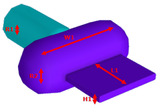
Side Rectangular Gate is defined as a box with parameters
(see Other Parameters below): L1, R1, W1, H1.For a Side
Rectangular Gate, LToLimitRunner= L1.
User-Defined Gate
This section describes the conventions for designing your own Gate types.
A Gate is a specific 3D part that describes the geometry of the Gate. A 3D part must satisfy some conventions to qualify as a Gate. This section describes these conventions.
- Hook
- The 3D part must contain a Hook with its origin at (0,0,0) and having the same directions as the 3D part.
- Type and subtypes of the Gate
- The type and subtypes of the Gate are defined by mandatory parameters:
These parameters have a string value. - Geometry of the Gate
- The geometry of the Gate is defined in a partbody called Gatebody.
- Gatebody represents the shape that needs to be removed from the Plates or the Inserts to allow the plastic to enter the part.
- The axis direction of the Gate is oriented toward Z+ by convention.
- The Gate axis origin is the origin 0,0,0 of the 3D part.
- The Gate may be endowed with small fillets with a radius always equal to the hidden parameter RSmallFillet.
- Geometry of the Runner
- It is useful to see a small section of the Runner. This small section is located in a dedicated body called VirtualRunner.
- It is arbitrarily shown as a cylinder with same axis as the Gate.
- The radius and length are defined by the parameters R1 and RunnerL (hidden).
- The parameter R1 can also be used to define the Gate, if required.
- The Runner is located above the Gate (taking into account the Z+ orientation) but no Boolean operation
is performed between the Gate and the Runner body.
- Visualization of the Runner
- An Injection Point is symbolically displayed as two cylinders; one represents the Runner and the other the Gate. At the time of creation of the Injection Point, the dimensions of these two cylinders depend on four dedicated parameters that must be present in the Gate part:
- L1Display: Length of the cylinder representing the Gate.
- R1Display: Radius of the cylinder representing the Gate.
- L2Display: Length of the cylinder representing the Runner.
- R2Display: Radius of the cylinder representing the Runner.
These are all string parameters. The value of these parameters is equal to the name of the parameter giving the dimension. For instance if L2Display=RunnerL, it means that the value of the parameter RunnerL is used to define the length of the cylinder. After creation of the Injection Point, no link to the Gate is kept. If the Injection Point parameters are modified, this is not reflected in the Gate. These parameters are hidden. - Mandatory Parameters
-
- The L1Display, L2Display, R1Display and R2Display display parameters are mandatory and hidden. They must be published.
- The type and subtype GateType and GateSubType parameters are mandatory. The subtype value None is acceptable. They must be published.
- The RunnerL (for length of the virtual Runner) and RSmallFillet (for radius of all cosmetic fillets) parameters are mandatory and hidden.
- Other Parameters
- L1: Length of the Gate along its axis.
- R1, R2: Radii.
- H1, H2:Dimensions in the Y direction. In rectangular sections, they correspond to the smallest
of the dimensions.
- W1, W2: Dimensions in the X direction. In rectangular sections, they correspond to the largest
of the dimensions.
All the parameters that are visible and not defined by a formula or a rule are included in the definition of the Injection Point. There is no lasting link between the values of the
parameters in the Gate and the corresponding parameters in the Injection Point after creation. These parameters must be published.
|


